Hello! This is my very first topic on this forum, thought I would share my scratch built joystick base. I got in to flight simming again for about 6 months ago (I am Swedish, and when I saw the DCS:Viggen I fell in love) As a kid (10 years or so ago) I used to screw around in FSX, and at that time I bought myself a used Hotas Cougar. When I got into DCS this time, I modded my Cougar with DIY evenstrain mod + hall sensors in the stick and the throttle. I have also lubricated the throttle with some Nyogel 767 and I absolutely love it! However, when i built myself some desk clamps for a center stick setup, the size of the Cougar stick base made it very unconfortable, with the edges cutting into my thighs, and having to sit very broad with my legs. Pics on mount build: https://imgur.com/a/3jN4plu. So I decided to build a smaller base to suite my needs better. I was for a long time not sure if I would pull this off, and that is why I am sharing this when everything is mostly finished.
First, I want to say that this is my very first DIY flight gear project. Also, I have exclusively used handheld tools. A lot of the work could have been more precise and tidy if using for instance a drill press, real metal cutter and so on, but I do not have access to such equipment. I guess I could have asked around and gotten some help with that, but this is the way i did it, and although it is not very pretty on the inside, I think it has a quite appealing look on the outside. Also, this is kind of a semi-budget project, and I have used a lot of materials I had laying around. I debated with myself if i would fit in a main board in the base, but I decided to keep my cougar main board instead, and use a cable with all 11 conductors to get the signals to the old cougar main board. I did this for following reasons:
- I absolutely love my Cougar throttle, and unless i want to mod it to be standalone USB, i will have to keep the cougar main board anyway.
- It will spare me some space in the base itself.
- It will save me money.
Maybe in the future, I will try to fit a small main board in the base, but for now, I am confident that this way will work just fine!
So lets get started ![]()
I have never used CAD, and instead i used a VERY simple (and free) “physics sandbox” software called Algodoo which allows you to draw simple 2D drawings, and also lets you spin things around. Perfectly enough for my needs. I guess i could share some drawings if anyone is interested. Then, I simply printed the drawings and begun the cutting.
The main materials i used for the construction is:
- Rectangular tubing 3x6 cm, 2 mm thick steel for gimbal construction. (Free)
- Rectangular tubing 2,5x5 cm, 2 mm thick steel for gimbal construction. (Free)
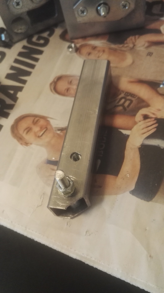
- Square tubing 2x2 cm for base stem (the part that connects to the grip). (5$)
- Bottom metal plate (reused from cougar) (Free)
- 10 x Flinged ball bearings 14 mm. (10$ including shipping from China)
- A variety of steel screws, nuts and washers. (maybe 10$ all and all)
- Sheet metal for welding the top lid. (5$)
- Black metal colour. (Free)
- 2 x springs. (19 $ including shipping)
- Stem connector (to connect to the grip), reused from cougar. (Free)
And for the electronics:
- 2 x Hall sensors SS495A1. (8$ including shipping)
- DVI cable with shielded conductors. (Free)
- VGA connectors for soldering. (3$)
- 2 x 7x7x7 cube neodynium magnets. (5$)
Tools i needed to buy exclusively for this project:
- 14 mm drill bit. (10$)
And lets not forget the sheer amount of Swedish snus consumed while building this! All and all, this project has costed me about 75$ + some equipment that i did not write down here such as glue etc.
This is the 3 parts which build up the main gimbal structure:

This is where it gets obvious that handheld tools has its drawbacks. The edges are not straight, the holes are not perfect and so on. But everything that needs to be square is square, due to the design, you will understand later. The middle part is the one that will sviwel, and the other two will be the supports.

Ball bearing placed into the hole.

And tightly secured with metal plate (which is ugly, I know).

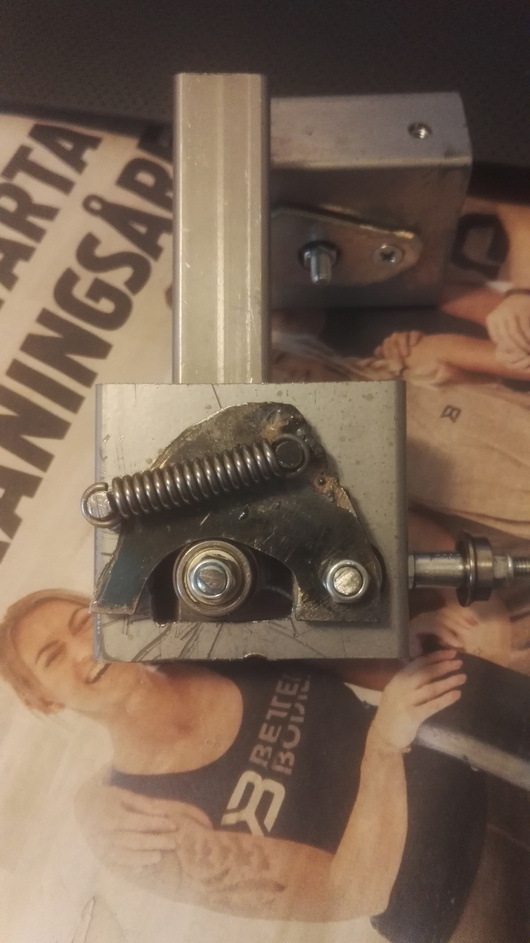
Moving on with the swivel part, here with cam-rolling bearing for the X-axis and spring screw mounted.
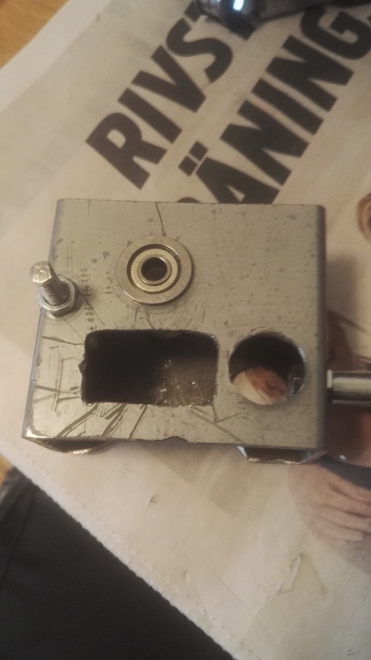
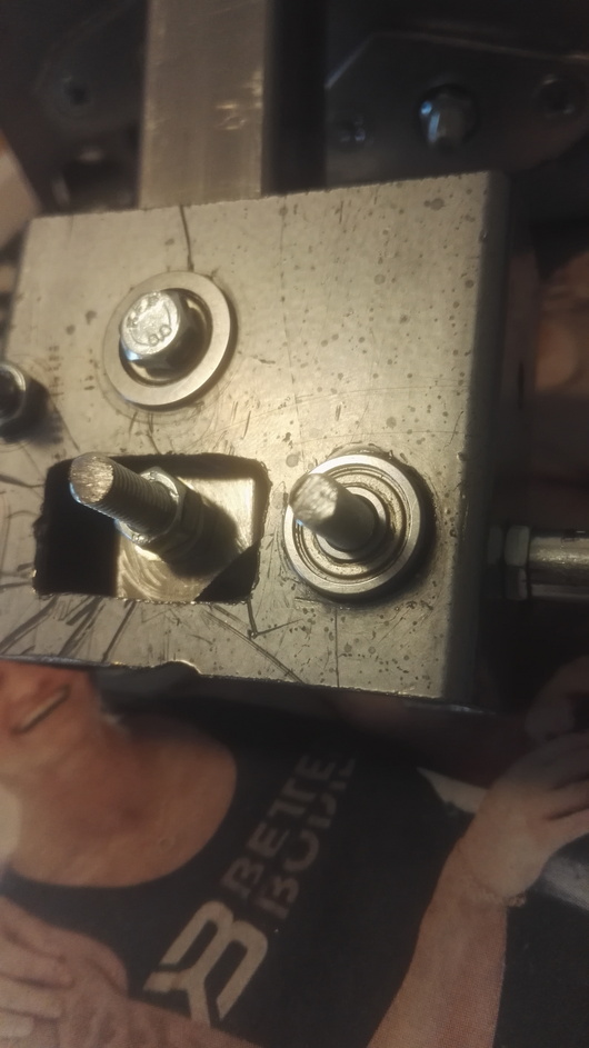
The stem part, with extendor nuts on the inside to allow for tightening of screws without deforming the square shape. The screw on the bottom is for mounting cam-rolling bearing on Y-axis.

Tightly secured, feels very sturdy, with zero play.
Cam-holding bearings mounted. Flinges on the inside this time in space-saving purpose on the inside.
Unfortunately, I did not succeed to perfectly allign these holes to let the screw go straight through (there is another bearing on the opposide side), and i had to enlarge the holes to allow for it to be straight. This created some play even with tightened screw, so I had to MacGyver a solution for this.

This is how i solved it; I cut small pieces of can foil and squeezed it inbetween the main part and the bearing. Nothing could move after that, and I then secured the foil bits with strong epoxy glue. It became very sturdy, and I am certain that this will hold (I tried to move it with all of my strength
The swiveling part assebled.

The same thing with the X-axis here.

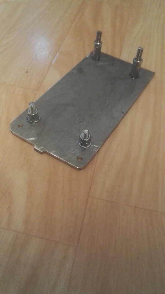
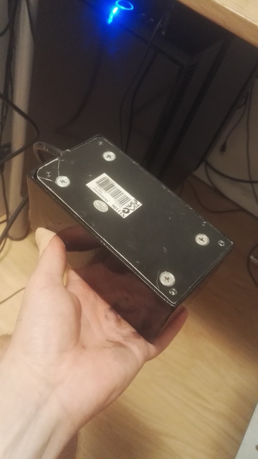
Bottom plate (reused from cougar). Drilled 4 holes for attatching to desk clamp.

The gimbal structure mounted on the bottom plate. This will be a fixed construction, to open the base in the future for maintainance etc, you take off the top lid part that will be shown shortly. In the upper part of the side supports, you can see that I epoxied nuts to allow mounting of the lid. The glue will not hold any structural support, it will just make sure that the nuts are in place when placing the lid over it, since I will have no way of holding the nut by hand on the other side.

Here, I have mounted the connector for the grip. I had to grind it down a bit to allow it to fit into the square tube. I mounted it in a slight angle (approximately 15 deg) since i will be using the stick in a center position. I was initially thinking to mount the connector with some screws that would go straight through the square pipe, but once i smashed the connector in, there was no way of making it move.

Shrink tubing on the springs for noice cancellation.

The top lid that I welded from 2 mm sheet metal. It was my first time welding, and I am not going to show you the inside (where the welds are), it is UGLY

Two layers of metal paint later.
Time to get started with the electronics! This part I have done before, when hall sensor-modding my original cougar.

The cube magnet goes straight onto the securing screw. Made some supports for the hall sensor, which then was glued onto the support. The same thing was done to the X-axis sensor.

Soldering all the wires to a VGA-connector (that will go into the cougar base).
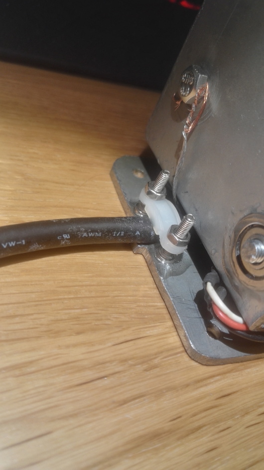
Made a clamping thingy to hold the wire in place. Also you can se the grounding wire here.
I first did this whole process with a wire that did not have shielded conductors. When i plugged it into the computer, everything worked fine, aside from a very pronounced jitter. I became worried that my method with a long wire to the main board would not work. A troubleshooted for quite some time, even replaced one of the hall sensors to see if anything would change. Finally, i disconnected everything from the main board (X-axis, Y-axis and the 5 wires to the buttons). Then, I connected just one of the axis, and the jitter was gone! Perfect precision! This way, I concluded that the jitter must be due to disturbances from the other wires (should have thought of this earlier). I found a DVI-cable that had shielded conductors inside, and did the whole soldering process again. When I plugged it in the second time, everything was working wonders!


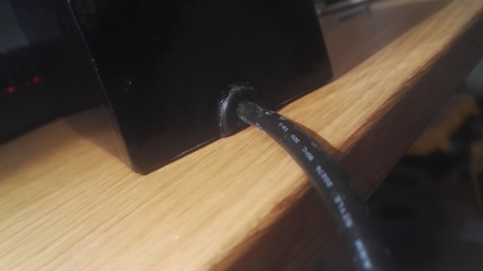
The finished cable with connector, which will go into the cougar base through a hole I made in the base, with a recieving connector on the inside. I might create a smaller box for the main board in the future, but one thing at a time

Time to mount everything. Here you can see the top nuts presenting themself very nice, making it easy to mount and dismount.
The back.

Here, I have mounted the base to my DIY desk clamps.
Since this base is significally smaller than the cougar, I had to make the metal mount plate the same size. Since the metal plate on the mount is made of 2 mm sheet metal (with holes in it even), there was a significant flex in the mounting plate. I fixed it by enforcing the plate in following way:
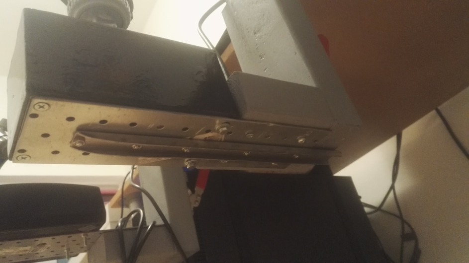
I cut some leftover 2x2 cm steel square tube in half, and secured it with small screws. Nothing is flexing anymore (besides my very weak desk itself
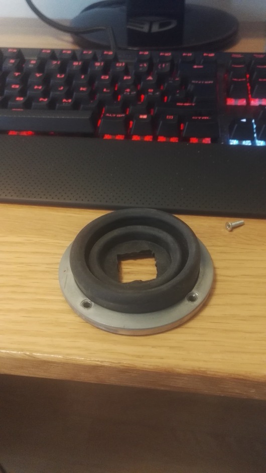
Now for the part that is left to be done, the rubber boot. What do you guys think of using this from the Cougar?

It is a little bit too big, but to my eyes it looks pretty good, and this beeing a semi-budget project, I think it will suffice. Please give me your thoughts on this
Creating the cams:
I did some research beforehand and tried to figure out what kind of force curve i wanted. I looked at a plot from Virpil, showing different cam profiles.

Source: https://virpil.com/en/blog/110-vpc-mongoost-50-new-cams-for-space-sims
I decided to go for the yellow profile, with no center, and a progressive spring force instead of linear. Here is a quick diagram i made over how I wanted my force profile to be, VS my old evenstrain cougar (which should be close to linear), and stock cougar (estimated).

I used the free 2D software Algodoo (if anyone is interested, I could make a youtube video to show how i did it), then printed the drawings out, and made the profile on 2 mm metal, using an angle grinder, and then very fine sand paper.
With everything assembled, the cams seem to be perfect. I can not feel any assymetry in force in different directions, and the movement is VERY smooth, I have never felt something this smooth in a joystick (then, I have not tried Virpil or VKB stuff).
The force is well enough to center the heavy cougar grip. As the above curve shows, there is not much force needed in the center position, which allows for great control and fine adjustments. Also, when reaching the maximum positions, the force is drasticly increasing, not quite needing to use two hands, but sure not far from it ![]() . After trying some formation flying in DCS, I am quite amazed of the smoothness and precision of this thing.
. After trying some formation flying in DCS, I am quite amazed of the smoothness and precision of this thing.
To sum things up, it is quite possible to build a joystick base, with only handheld tools, and not exceeding 100 $. The next step is to watch @Troll molding his Viggen stick, I would love to have that beauty connected to my base!
After long time building and no flying, I will enjoy flying for a while now, but this DIY thing sure is addictive. Thinking of building rudder pedals next, but we will see about that ![]()
Hope that you will enjoy this build thread!