737DIYSim Bell 212 Cyclic Build Thread

So I an effort to up my sim’ing I could do something simple like add an extension to my VKB, but why not go whole hog? Enter the 737BIYSim helicopter controls. I am starting out with the cyclic and will be adding the collective (and pedals when he releases them).


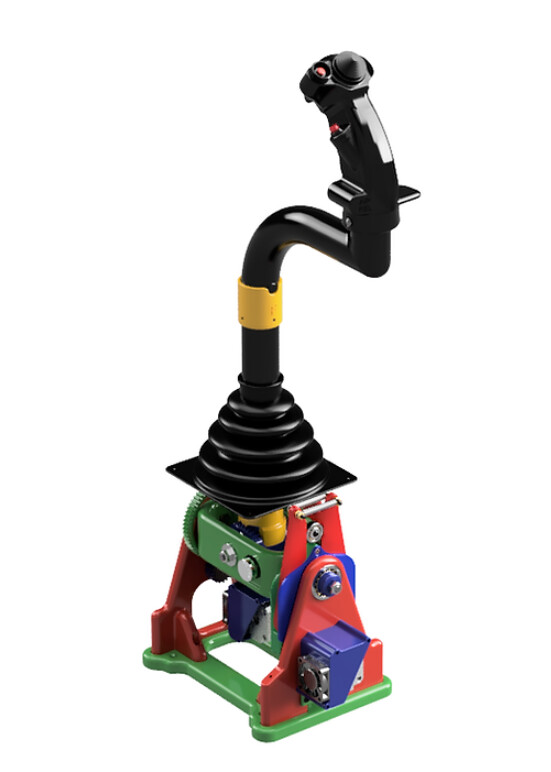
The two major draws for me are the fact it features “magnetic brake” type trimming, and beep trimming completely independent of the simulation that’s being used (he shows that off around he 11:30 mark). It is physically holding the stick in place, or moving it incrementally via button press. Is this 100% realistic for all helo’s, heck no, but I really appreciate the quality of life it while provide coming from a non FFB stick.

I have finished printing all the parts for the cyclic, have gotten the rotary hall sensors, bearings, and have just ordered the hardware (bolts and screws). I haven’t ordered the Arduino, stepper motors, etc yet. I’ll get those next.

So far I’m in for about:

$48 for the STL and CAD files to print (I wanted the CAD files to have if I want to make changes later)
$25~ for the bearings
$10~ half a roll of filament
$15~ for the hardware
$46~ for the hall sensors

$144~ so far, with about another $100 on the electronics.

Cheaper than a commercial stick? Well thats depends on what you are after. For a full size fully functional FFB model, heck no, I’d need to add at least a 0 to the end of my costs to get even close. Compared to a Logitech desktop stick, sure it’s pricey. I am also buying supplies for the cyclic, collective, and control box all at once (hence all the ~ costs versus hard numbers) and it’s going to be probably around $300-$350 all up for a full setup. With some relatively minor changes I should be able to use it as a flight stick with swapable stick and throttle grips, and beep trim.

The printing went off without a hitch, everything fits together nicely with only minor sanding required. He’s done a very good job of putting this all together, the build guides are very nice (they’re accessible on his website for free), and the assembly videos are very helpful. A better sorted parts list for bolts and screws is my only gripe, and 10 minutes in excel took care of that for ordering. I’ll put up some pictures tomorrow of the various pieces mildly assembled, and once the hardware arrives to screw it all together I’ll add build pics.

So far it’s a fun project, nothing frustrating, and I’m looking forward to seeing it all take shape.

8 Likes

A friend of mine built that cyclic and he’s very happy with it.
Please post more pics of your build!

Oh I shall, right now though is a fairly uninspired box of 3D printed parts with bearings inserted. Once all the bolts get here that should make it much more interesting.

1 Like

I realized I had actually forgotten to print out the base, and the curve of the stick. So while the printer is running those, please enjoy the box of parts waiting assembly.

Bearings have been installed, and most of the sanding is done on things that need a good fit. Might be one or two spots I’ll find later but overall that’s 95% of the cyclic right there.

3 Likes

Nice!
What kind of material did you use?

PLA, I’ve had good luck with dimensional consistency with it. So far seems to be true here.

1 Like

Are the parts files stl or does he send them as ready made g-code for your printer?

They are STLs, which was nice as it lets me print a bunch in one go. He has a printing guide as part of the build guide so all the settings are there, and it’s pretty consistent across all the parts.

Also with the staggering array of printers a default gcode might be problematic.

He also has several variants, for example the hall effect sensors versus pots, and the small printer bed mod, which break up the base and stick curve into pieces to let them run on a smaller printer like the Ender 3.

If you purchase the CAD file version it comes with the code to view and download all the files from Fusion 360 (I think Id have to check if it’s fusion or Autodesk).

2 Likes

And in my hubris, I thought there was enough filament left on the roll to print the larger part. There was not, and of course there was enough to print the smaller part.

Season 3 Mistake GIF by The Simpsons

Any nearby plastic pushers…?

1 Like

Oh that’s the worst part I had 3 spools I could have thrown on there and didn’t. Oh well it’s off and running on a fresh spool, it should be done this evening.

2 Likes

So first off the part I tried to print, what I finally printed, and what I should have run the first time to not waste that filament. Oh well.

Next up is the gimbal assembly mostly together minus the electronics and the springs. Electronics are on order, so I should have everything assembled in the next week. Actually working, well we’ll have to see about that.

Two more very minor complaints, you actually need 12 M4 nuts, not 10. Also, rather than about ~1’/300mm of piece of threaded rod, you could do the same with 2 M8 bolt’s and not have to mess with cutting the rod.

6 Likes

Point of note, the connector in the picture above (the white part inside the black unijoint body with the gear teeth on the front) along with the curve portioned pictured, is sized in metric. PVC in the US is not in metric. I am debating just ordering a piece of 40mm PVC off amazon, as my two alternatives are mess with resizing the STL’s, or sanding and cutting the PVC extensively.

Addendum, I could print an adapter to go between the two cyclic parts and the PVC, I think that’s going to be my option. We’ll see how it goes.

Addendum to the addendum: Per the wife “Just order the dang thing.” So 40mm piece of PVC on order.

The best thing about rural irrigation/plumbing is that 1" or 2" BSP is close enough to 25mm and 50mm poly pipe that fittings are interchangable… provided I apply my usual method of:

If it doesn’t fit, use a hammer. If that doesn’t work, use a bigger hammer. If it breaks, it needed replacing anyway :crazy_face:

Probably not the best approach for this job though :thinking:

2 Likes

Oh believe me my initial thought was, hmm that ends chamfered big enough hammer ought to get it in there. Then I decided the amount of printing time if it broke wasn’t worth it.

2 Likes

Sorry for the lack of updates.

PVC pipe arrived, required a bit of sanding and working to get everything fitting as it should. Some of the electronics arrived via quite literally the slow boat from China. I believe I have everything I need to start wiring things up. Here is the cyclic assembly minus the stick, which I am waiting for the humidity to cooperate to prime and paint, and a few other bits to avoid having to keep dissembling things.

At some point I’m going to figure out a connector to interface different stick tops so I can swap them out. I have plenty of button and axis space between the Bodnar board and the Arduino to run pretty much anything I can wire up. I also need to do the same for the wire loom coming off the cyclic base to the control box housing the stepper controllers and control boards. I prefer to be able to detach the cables for ease in setup and transport if possible.

Question for the MS electronics crew, I am not familiar with the style of post connector on the rotary sensors.


I would normally assume those are simply wrapped and soldered? Or is there a better option I’m not aware of? As an aside if you build this, pay attention to the orientation of the gear you install on the sensors when assembling it to the body. There are no end stops on the rotary sensor, if the gear is not TDC you can end up doing what I did which was being so far off center that suddenly having your axis go from far left and wrapping around to far right is not optimal. Of course, this required significant disassembly to rectify.

I’m off Saturday so I plan on installing the breakout panel for all the sensors, fans, steppers, and wiring them to it. Also everything is here to wire up the control box, so I’ll get started on that as well.

Second question, does anyone have a recommendation on a 24v power supply?

4 Likes

A Meanwell LRS-350-24 should work fine. It’s a common 3D printer PS.
I think I have a spare, but you can probably find one closer to you that is cheaper than shipping mine over.

https://no.mouser.com/ProductDetail/MEAN-WELL/LRS-350-24?qs=ah3jBNVE1PT%252BkwLcackrGA%3D%3D

2 Likes

Work continues…

I accidentally ordered a hat switch that includes a rotary encoder, not sure what to do with it, but it made the wiring more a hassle than I was planning. I am wiring these long enough to not need a separate connector in the stick extension. The plan in the future is to figure out a solution to allow for multiple grips that can be interchange and connected without having to fish 3’ of cable through the extension.

That’s what I was looking at, I think I’ll go ahead and get one.

It’s almost hard to find one without an encoder… I have one for my Viggen stick and I’m considering to lock the encoder out mechanically.

Power supply on order, once it gets in, I’ll hit the local hardware store and figure out an enclosure and breakers for it. The stepper motor controllers pull a max of around 4 amps, so with the 80% rule of thumb I’m thinking a 6amp breaker?

Got the stick finished and mounted, just need to drill everything and screw it all together. Off starting tomorrow so hopefully have it largely finished by the end of the weekend.

Also printed out a B8 grip (found here Century Series Grip - F-4 Phantom Joystick + Many Aircraft - Updated B-8 Grip by TheSimNet - Thingiverse) that I’m going figure out my grip swap options out with. It has the same number of buttons and hats, so it should just be the mechanical connection part. After that I’ll look into changing the number of buttons and hats.

3 Likes