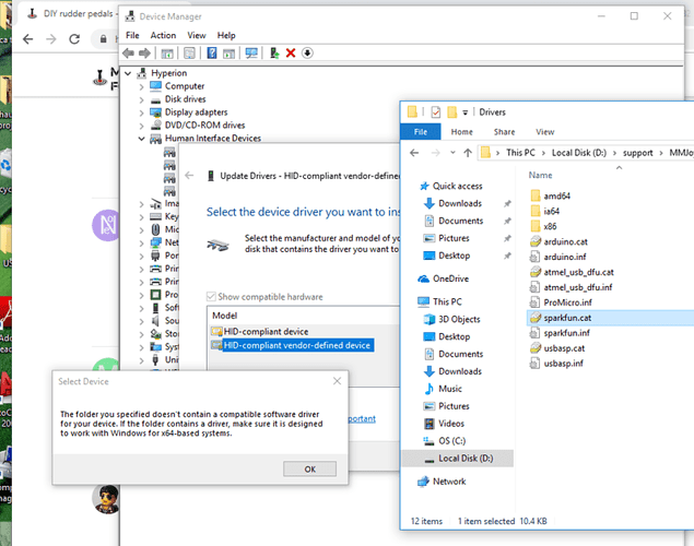
So once my Pro Micro board comes, I can plug it in via the USB to computer to program, correct? Then its ‘stand-alone’ and I wont have to hook it to an arduino board for it to operate?
Correct.
Once you have installed the MMJoy2 firmware, you can program it via the MMJoy Setup software (same software that you used to install the firmware).
Once you have set everything up, the ProMicro controller will be seen as any other Game controller.
Sounds easy ![]()
Once I will run out of my MaRS sensors ( my joysticks scrapyard ) I will also have to go that way.
That board is insanely small; how do you mount it? I was thinking of epoxying it onto a lego block.
I soldered pins to the teensy controller, and mounted it to a PCB.
Are you following this info.
What controller did you say you had? Arduino micro or Sparkfun Pro Micro?
Pro Micro clone
actually I am getting some kind of signal to the software. If I look at the ‘Direct Input Viewer’ screen and I move a magnet in front of the Allegro1324, I see changing values but they dont seem usable… Can you tell me what values to enter (or how to calculate the correct numbers) on the ‘Joystick Axes’ screen; I dont have anything to go by, so I just put in some random numbers as placeholders…
THanks
Here is my franken-tester rig. I have the Allegro Hall sensor connected to the Pro Micro and I’m looking at it via the MMJoy program. Just kind of at a loss as to where to go from here…
It’s a bit hard to tell from that picture, but how have you wired that hall sensor?
It should be wired like this
Pic from leobodnar.com
Is that big metal thing the magnet?
If so, how is it polarized?
What type of hall sensor are you using?
Um, actually no. Sensor is A1324L UA. I wired it for ‘LH’ instead of ‘UA’. (something to be said for careful reading…) The’big metal thing’ is a neo magnet from a HD that I ripped apart. (it was just acting as a stand in to get SOME response from the Hall. The ‘production’ magnet is one of the hollow ones you recommended. So since I swapped the GND and Signal legs, I am getting a coherent output from the Hall RE the ‘direct input viewer’.
Just don’t know how to ‘harness’ that and make it usable.

Ok…
I’m not the most electrical savvy guy on the net, so bear with me.
I have used the A1302 sensors. They are now replaced by the A1308.
The A1302 has an output of 8V and the A1308 has 7V. The A1324 you’re using has 15V… I don’t know if this is useable?
I can put a few A1302’s in an envelope and send to you. I could also try wiring one up and set it up in MMJoy2 and see if I can get that to work.
Thanks for the reply Toll: When I look at the spec sheet, I’m not seeing the output of 15V. Is that calculated somewhere?
If its only using ~5V as Vcc, that A1324 chip doesn’t look big enough to house an amplifier so it seems output should vary between >0 and <5 VDC, or am I missing something.
I appreciate your offer to send some 1302’s, but shipping from the Far Side of the World would probably exceed the cost of buying them in 'Murica. If we determine that the ones I have aren’t suitable I’ll grab some from Amazon. Thanks.
Also, the crescent shaped neo magnets are kind of interesting, so I might try them for the toe brakes…
I just tried to compare the datasheets to see if there were differences. Don’t know if that output voltage is significant.
Did you try using the diametrical neo ring magnets?
The magnetic flux must flow through the hall sensor for it to register any angular change of the flux.
If you have an oscilloscope or multi-meter, it would help to probe the output of the sensor while you place the magnet in position. This way you can adjust it to the quiescent state (output should be around 2.5V, with a 5V power supply) and you can check the output at max deflections.
There ARE amplifiers in the sensor, but the fact that the datasheet states Absolute max Vcc of 8V AND max Vout of 15 implies gain and that gain is really from the sensitivity of the sensor: 5mV/G. I don’t know what the output of your magnet is, but if it put out say, 500 G, you would get an out put of: 2.5+(.005*500) = 5V.
If you find that you are overdriving your controller board, just position the magnet further from the sensor – it shouldn’t be far. If you really wanted to protect your controller board, you could clamp the sensor output with a zener.
BTW, just so you know I’m not just some random guy giving advice on the internet, I’ve been designing mil aviation electronics and medical electronics for a couple of decades now.
does ‘quiescent’ mean neutral/center position?
here is how the Hall and magnet(s) fit together in the grand scheme of things. THe magnets will rotate around the sensor.
Are those two magnets on top of eachother?
Being diametrically polarized, won’t that make them cancel eachother out? ![]()
You are correct. Good catch. I hope a single magnet will have enough Gs(?)


