How To Use the Doppler Navigator in DCS: Mi-8MTV2
By @EinsteinEP - January 23, 2015
Originally published at: Articles - Mudspike Forums
One of the less understood systems of the Mi-8MTV2 is its ДИСС-15 doppler navigation system. Similar to the doppler navigator installation on the Ka-50, the Mi-8 has an array of sensors that use the Doppler Effect to determine the relative velocity of the helicopter over the ground. By bouncing a beam of a known frequency off the ground below and then detecting the change in frequency when the bounce arrives back at the helicopter, the equipment can estimate the relative velocity of the helicopter with high precision.

Animation of the Doppler Effect (Courtesy wikipedia.com)
Doppler Navigation
This method of velocity measurement gets tricky if the ground isn’t stationary, or if the surface that is bouncing back the beams isn’t compatible with your sensors (e.g., some radar wavelengths have issues with water). The ДИСС-15 has a special mode for flights over water, and pretty much thinks you’re screwed if the ground is moving underneath you, but you should be covered for most situations. Regardless of the surface, the sensors don’t work so well at altitudes greater than 3 km above the ground and anywhere even remotely close to the speed of light.
If you remember your basic calculus courses, velocity integrates into position – i.e., rate * time = distance – so the summation of repeated velocity measurements from the Doppler measurements will add up to a net change in position from wherever you started the summation (aka “integration”). There is a navigation panel on the co-pilot’s console that does just this for the Mi-8, but it can be a little tricky to set up and use for the uninitiated.
First, Turn It On
Before the ДИСС-15 can be operated, it needs to be supplied power. I know, right? The power switch for the ДИСС-15 is on right triangle control panel (near the copilot’s seat) and should be engaged after the engine generators are up and running.
 The ДИСС-15 power switch is on the right triangle panel.
In addition to power, the system needs to be set to an operational mode. On the bulkhead behind the copilot is a control panel with a rotary dial. The far right position, РАБОТА (“working”), enables normal ДИСС-15 operation while the other positions are test modes. If neither the КОНТР. (“test”) nor РАБОТА buttons are lit, there’s an electrical issue somewhere and the ДИСС-15 will not operate as expected.
 The ДИСС-15 mode panel is on the bulkhead behind the co-pilot.
What Have We Here?
Now that we’ve got electrons flowing, let’s take a look at the co-pilot’s display.
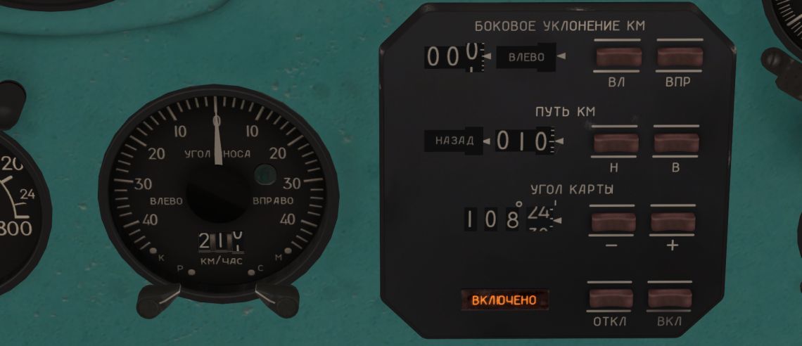
 The ДНСС-15 display on the co-pilot’s side of the office.
The top readout, БОКОВОЕ УКЛОНЕНИЕ (lateral deviation), is the cross-track estimate. The numeric readout is in kilometers and the label next to it indicates ВЛЕВО (to the left) or ВПРАВО (to the right). The next readout, ПУТЬ (path), is the along-track estimate, also in kilometers, with labels for НАЗАД (backward) and ВПЕРЕД (forward). All of these readouts reflect the integrated distances relative to the course that has been entered into the navigation panel. Note that the course heading input on the third and final readout is expected in degrees TRUE, not MAGNETIC. More on this later.
Once the input conditions are set, the ВКЛЮЧНО (“on”) button commands the ДИСС-15 to begin integrating those doppler velocity measurements into a delta-position estimate. The ОТКЛ (“off”) button pauses the process, freezing the current solution, but doesn’t reset any of the readouts – you’ll need to do that manually. Always be sure to “switch on” the integrator before you takeoff or the ДИСС-15 will happily do absolutely nothing for the remainder of your now-longer-than-expected flight.
The dial to the left is the drift indicator which shows the angle between your ground track and the nose of your aircraft, e.g., a reading of 5 degrees to the right means that your ground track is heading 5 degrees to the right of your nose. At the bottom of this dial is the measured ground speed in kilometers per hour which is helpful in estimating time of arrival. The switch at the left toggles between test mode, “К” (for КОНТРОЛЬНАЯ РАБОТА) and normal operation, “Р” (for РАБОТА). The switch on the right toggles between sea, “M” (for МОРЕ) and land, “C”, (for СУША)
Keep It Steady
There is an indicator on the pilot side of the aircraft that displays the forward and backwards relative velocity as well as vertical velocity. This is incredibly helpful in maintaining a hover in low visibility conditions – e.g., night, dust, snow, fog, insobriety. The display doesn’t indicate until you’ve reached 5 km/hr or so, so it’s not good for super precise hover control, but should help you keep from drifting away too rapidly. This display only works when the Mi-8 is moving less than 50 km/hr and is more than a few meters off the ground.
 Mi-8 pilot’s doppler velocity indicator.
Different Methods of Doppler Navigation
I use the ДИСС-15 Doppler Navigator in one of three different methods: FROM, TO, and GRID. Both the FROM and TO method require the co-pilot to enter the desired course into the device. With these approaches, the cross-track value represents the cross-track error from the input course line starting at the point when the integrator is started.
The interpretation of the FORWARD/BACKWARD value depends on whether the system is being used in the FROM or the TO method. In the FROM method, the FORWARD/BACKWARD value is initialized to zero and, in flight, represents the distance FROM the original waypoint (where the ДИСС-15 integrator was first enabled). In the TO method, the navigator sets the FORWARD/BACKWARD value to the distance to the intended waypoint and then the FORWARD/BACKWARD value represents the distance TO this final waypoint. Nifty, eh? One of the challenges of either of these methods is that changes in the flight plan (e.g., diverting to another field, encountering weather or enemy, etc.) is pretty much disastrous to the in-process navigation solution. It takes a sharp co-pilot, good charts, and some nimble fingers to update a solution on the fly.
In the GRID method, however, the course is left at 0 degrees to represent true north and the RIGHT/LEFT and FORWARD/BACKWARD values are set to some grid reference point – often zero, zero to represent the initial airfield. In this mode, the RIGHT/LEFT value represents the distance WEST or EAST from the reference point, and FORWARD/BACKWARD represents the distance NORTH or SOUTH. With a little careful plotting, a navigator can easily determine relative grid coordinates for any waypoint and, conversely, be able to accurately determine the helicopters position for any given readout. Personally, I find navigating to a specific waypoint using this method a little counter-intuitive, but I’m sure that with a lot of practice any pilot can get it down.
Here is a graphic illustration of each method to enhance confusion.


Confused? It’s no wonder, there’s an awful lot to soak in here. Stay tuned for an after action report where I use the TO method to navigate my way through a mission.
Getting Measurements
The ruler tool in the F10 map view is an extremely convenient place to get distance and bearing information for legs of your flight, but there are two important considerations that you need to keep in mind. First, the distance is given by the ruler is in nautical miles but the ДИСС-15 takes kilometers as input and, second, the heading information is given degrees MAGNETIC, not TRUE. The first challenge is easily overcome by applying a constant conversion factor of 1.852 kilometers per nautical mile, but the difference between magnetic and true headings is not so easily solved.
A TRUE heading is measured from the direction to TRUE north pole and a MAGNETIC heading is measured from the direction to the MAGNETIC north pole. This difference is called magnetic declination or variation and changes depending on where you’re at on the surface of the Earth. To make matters more complicated, the magnetic north pole is actually moving, so the magnetic declination changes for a given location year to year.
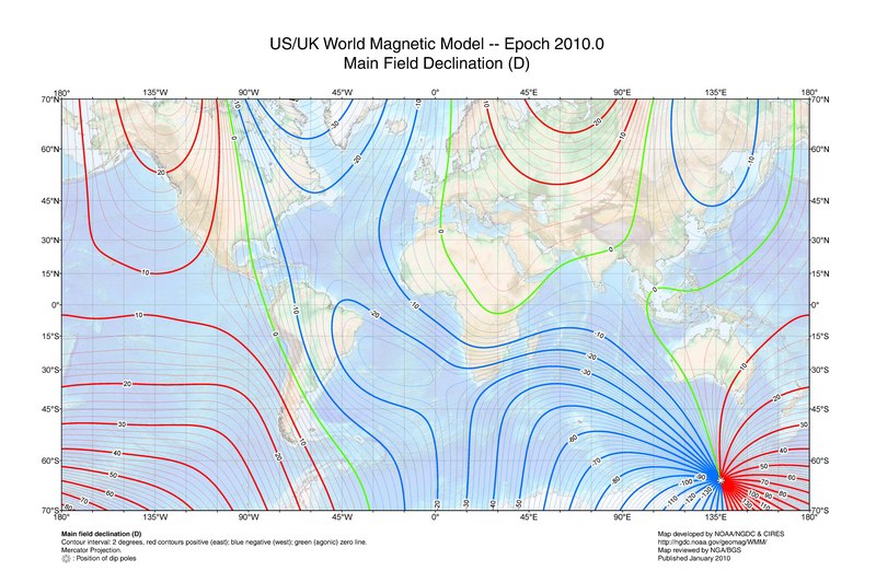 Magnetic Deviation Map (Courtesy wikipedia.com)
Unfortunately, other than the A-10C’s CDU, there is no easy way to get magnetic declination in DCS World. However, I did find shu77’s extremely handy DCS World airfield diagrams which includes all sorts of great information about airfields in DCS World, including magnetic declination. Look up the nearest airfield, subtract the variation from the heading given at the top of the F10 map, et voila!
Just Walk It Off
A Doppler navigator will have random walk errors in the navigation solution that build up over time. I don’t have the data on the Mi-8 sensors, but in my experience, I haven’t encountered any noticeable impact on legs as long as 80 km. Much longer legs could build some serious errors. If you are planning to use the ДИСС-15 to execute a really long cross-country, pick a few points where you can fly over a known position and reset your navigator to those points. For example, for a 100 km journey, you might set a waypoint on bridge that’s about halfway between the two points. Deliberately overfly the bridge and adjust the cross-track and along-track error to match your planned values for that waypoint and you are effectively removing any navigator drift. This can be a little tricky to execute, but with a little forethought and planning you should be able to maintain very accurate navigation for very long routes.
Summary
The ДИСС-15 is a simple tool that can be used for simple navigation legs, like my example above, or a complex route with multiple waypoints. The system isn’t as convenient as a GPS or flying map, but is quite functional and enough of a challenge to be satisfying without being tedious.
I hope you enjoyed this little tutorial, be sure to give me feedback and comments. I’d love to hear how this little experiment worked for you!