MMJoy PCB design

G’day guys

I’ve been tinkering on a few things (with some 161 SQN colleagues) and looking at getting some custom PCBs cut (for an A-10C CDU project) to do a proof of concept and test out the capabilities and QA of the PCB manufacturer though we needed to do a test run of some thing smaller/trivial to validate it.

We started out with an arduino-micro/pro-micro/teensy style board in size but wanted to maximise the pins utilised so went for the longer (teensy++ esque) style.

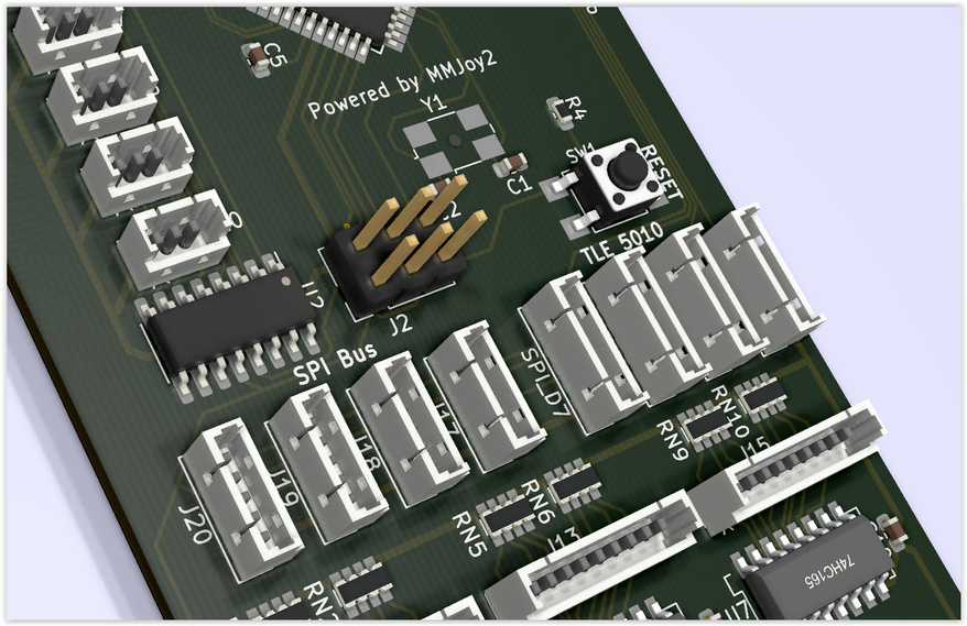
These boards are all spec’d for the ATMega32u4 chip which we normally flash with MMjoy,
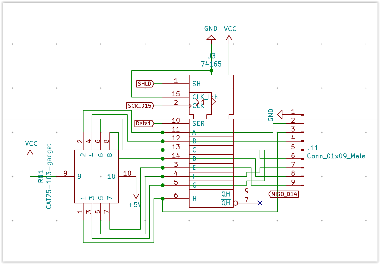
but then I started adding shift registers to the design, because most times we’re using one of these - we’re building a switch panel… so it made sense to make a board with everything you’d need on it.

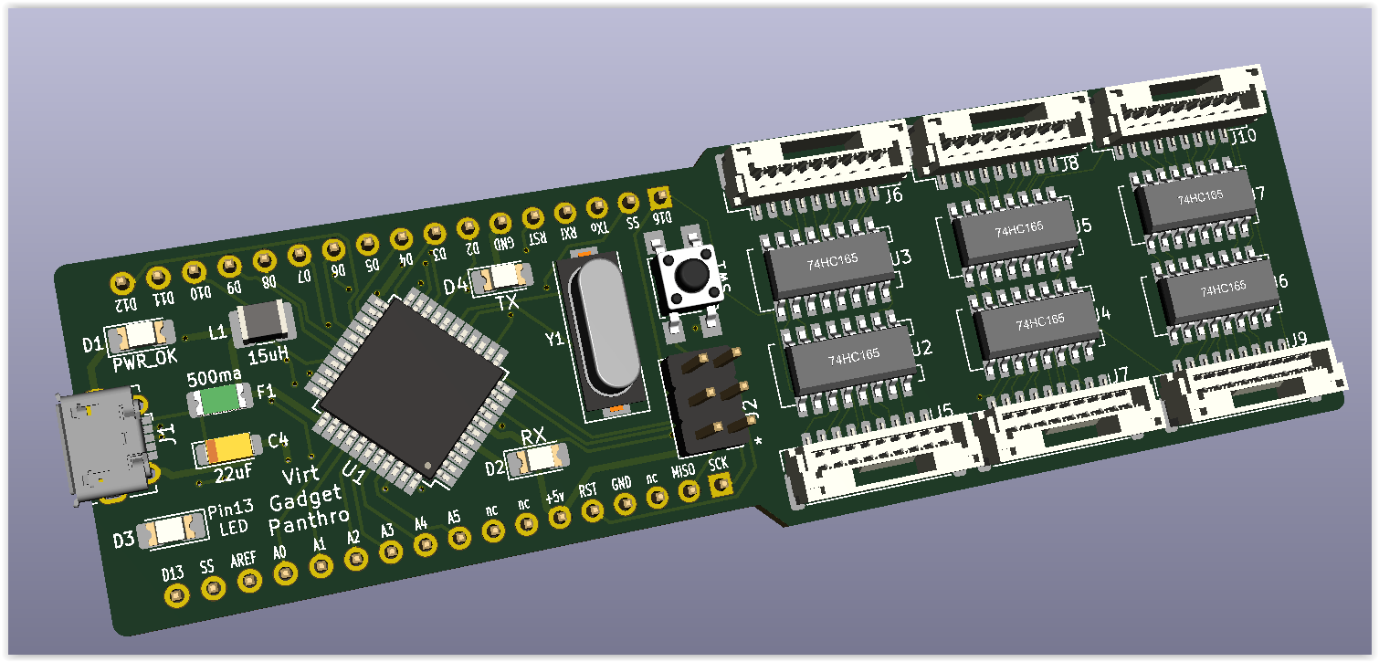
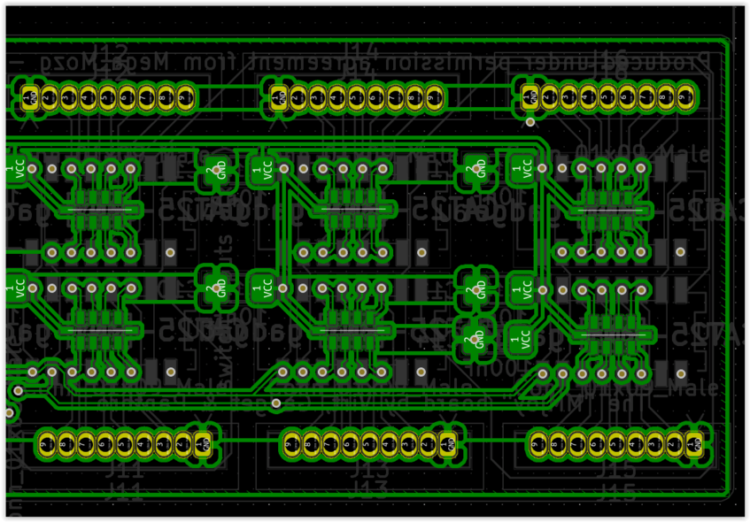
Originally it looked like the unholy birth child of a arduino and a shift register dev board…
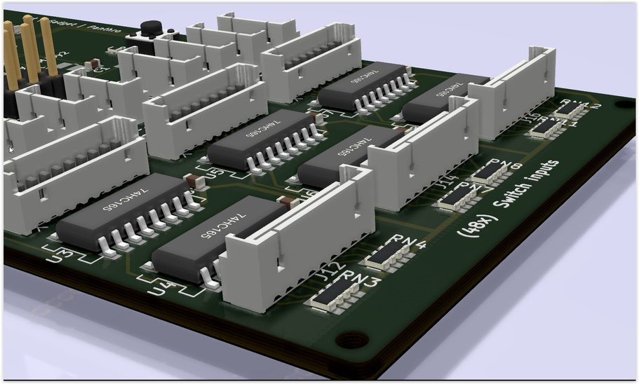
but then ‘virt’ decided to remove the pin headers and simplify it so that newbies would potentially be less confused and be more inclined to tackle it.

Granted we removed a lot of the flexibility by removing the pin headers… but if they are clever enough to be doing that, then they dont need the MMJoy board (built for beginners).

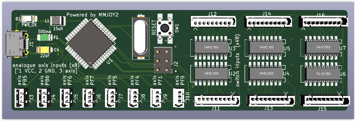
For the beginners though adding small JST connectors for each axis, & labelling the axis ports with the pin label as seen in the MMjoy interface, (not the pin IDs that arduino use), which will make configuration in the MMJoy interface that much easier.

Boards will also be shipped with (8x) 1x3 & (6x) 1x9 JST connectors with ~20cm < 30cm wiring looms.


& ironically the above picture has neither the 1x3 or 1x9 pin connectors… (humor me, please)

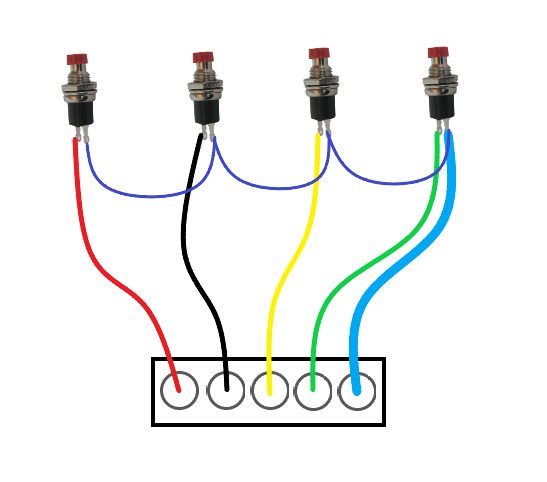
All you have to do is solder the ends to your switches & plug it in.
you will need to join the ground pins on each cluster of 8 switches together for the shift registers to work. (picture here is obviously only 4… just add 4 more and keep joining the GND)
Wiring_gnd

I’ve been trying to contact Mega_Mozg on ED & Virpil forums, to get permission to put MMjoy on these boards prior to shipping, which would simplify end-user usage even more, (haven’t heard back yet, but touch wood - also if anyone knows Mega_Mozg personally please let him know about these boards).

Whilst we are looking to sell these boards, mostly just enough to cover the costs of production, we are under no illusion that this will be a commercial gold mine for us, so it will be to a small niche of users, mostly flight-sim folk like us, perhaps car-sim enthusiasts as well,( some are even trans-genre :rofl: ). It is unlikely they would end up in commercial enterprise product, which this board is very much NOT designed for.

These (beginner) boards will no doubt be used in users flight sims, DIY panels etc. as such we would like to be able to send them out pre-flashed with MMjoy.

If permission is not forth coming though, we will simply send them out blank with instruction included on how to flash with MMjoy, which will still meet the end-user agreement.


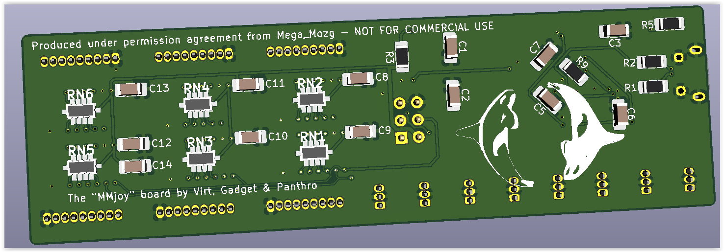
***** Please note: permission is pending - this is purely a 3d Render of the proposed end product *****

The logo is one of my original designs back when i was studying 3D animation & I used this as my business logo; see https://avimator.net (this is a very old site - i haven’t updated it since it was put in place, the business never really got off the ground, no traction.)

We’re almost ready to get some of the boards printed, we’ll have a few spare from the sample batch & if they’re all OK (as hoped) we can move these on, (we don’t need them all). If they prove popular we might make another small batch.

All credit goes to ‘virt’ for this one who kicked us off on this path and from his original ‘DIY-arduino’ board, assisted me in the design & layout of the MMjoy board. Virt’s electronics knowledge is the only guiding light we have in a sea of chaos as we blunder through the unknown.

cheers

10 Likes

That looks awesome! Let me how much and if I can grab one or two when they become available!

no worries… just keep in mind that there is nothing ground breaking about this technology.

It is currently available by simply purchasing an off the shelf pro-micro board and dev board with shift registers, following the instructions on my speel at Shift Register - 229ahb its easily achievable

However this board is simplifying a lot of the wiring interconnectivity and the assignment of MCU pins, aim being to take the headache out of some of the initial hurdles that trip up first timers. It is therefore targeted at novice users, unfamiliar with electronics, who want to build their own switch panels, but lack the expertise to attempt it.

I’ve had so many ideas over the years that have been lost opportunities, simply because I lacked the expertise in a certain field to see them to fruition. I also don’t have a mind for business at all.

I’d rather not see that sort of disadvantage perpetuate in this day & age where the technology is there and so readily accessible. Im the sort of person who would climb in & drag you out of the mud, rather than some who would simply step on your head just to keep their shoes clean.

Cost is yet to be determined, & we are looking at 3 options :

  1. DIY kit - MMJoy board, all components & cables (cheapest, covers bare cost)
  2. Partial DIY kit - MMJoy board with all SMD components pre-soldered, only the thru hole components are DIY + cables (removes the difficulty of intricate SMD component soldering)
  3. Pre-assembled - MMJoy board fully assembled & cables (cost + a little bit for labour)

we dont want to tear anyone a new one, but we would like to at least break even

cheers

1 Like

Very cool, @gadget!!
Wish something like this was around when I fell down this rabbithole, some years ago.
I’ll send a message to Vitaly.

1 Like

lol: you’ll never guess what our discord chat group is called… :nerd_face:

much appreciated re: contacting Vitaly, I’ve never conversed with him, didn’t know him by anything but Mega_Mozg (until now) . I’ve left two direct messages for him in the Virpil forums, (Sokol on ED forums suggested I try to contact him there), but I dont think he has seen them yet.

2 Likes

I’m really impressed with this controller, @gadget!
But no love for TLE sensors?

1 Like

We’re investigating (& testing) some options at the moment;

  • increasing to 12 bit res instead of the 10 bit inside the mega
    (so 4096 positions instead of 1024)

  • added bonus of freeing up pins on the mega.

  • more connectors for simplifying connecting other devices (TLE5010 included).

Again, this board design isn’t doing anything new, that cannot be done already…
it’s purely simplifying it to make it easier to connect to and configure it.

That said though - to create some additional value, we’re trying to improve the design slightly so that its more than ‘just an arduino & a dev board’, but also a more user friendly unit.

Hopefully should have some more details to share shortly, we were almost ready to go to print, but are revisiting a few features to improve on slightly, we’d rather take a little longer and refine the design to have the best possible end product than something that will just do.

3 Likes

Gadget, make sure you have some debounce on those switches, not all 165 have internal pull-up/down resistors! You could get a lot of ghost inputs!

Other then that, looks near!

1 Like

Hey there @TheAlmightySnark
Negative ghost-rider, (the pattern is full). :sunglasses:
have a gander directly under the 74hc165 chips, on the reverse of the board
ResNets… (hard to pick when the SMD stuff all looks pretty much the same)
also added in bypass capacitors… maybe overkill, but trivial cost :nerd_face:

unless I’m missing you’re point entirely…

1 Like

Nah I think you got it, I was looking at this picture:


And seeing all those switches unbounced made me a bit worried!

Looks like a lovely board that ought to help a lot of people!

no worries, had me worried for a second… :fearful:
that picture was just to show how to wire up the little JST connectors that will come with the board to any swtiches you want to connect to. The board will handle everything else

maybe this will clear it up

it’s easier to see in the BUS modes

the switches coming in through the connectors are connected to the respective pins of the 74HC165 Shift registers

and each of the pins of the shift register is connected to its own Resistor Network (on the reverse of the board)

hope that makes it a bit clearer

cheers

3 Likes

Yep clears it up!

Do keep in that mind that the 165 may have internal pull down resistor which would in theory allow you to eliminate the register bank, though I think I once accidentally ordered the fancy ones so… yeah…

1 Like

We did research these 165’s and werent actually able to find any with internal resistors, hence the resnets.

Originally we were planning on offering it as a complete DIY kit and were trying to limit all the SMD components to 1206 to make it a bit more managable, but we couldn’t source an SMD resnet in that size so we opted for 8 individual 1206 SMD resistors (per 165) …


which chewed up a lot of room, so we ended up ditching that idea and went with the resnet as illustrated

2 Likes

And I thought my design was sooo tight…! :laughing:

3 Likes

oh hey! - thats cool @Troll
I didnt even realise you had created one - kudos dude
(finger on the pulse - I have…)

i especially like the line of female pin headers so that you can drop in a new controller board if anything goes wrong, i did a similiar thing on my A-10C UFC panel design

3 Likes

Have you thought about making ”satellite” Shift register boards? I did some smaller PCBs for mounting inside tight compartments like handles and such. At least put a connector there?

image

2 Likes

yes indeedy, :upside_down_face:
virt & I were discussing that very thing late last night/early this morning
we already have the pin headers for the programming module to connect to
virt mentioned placing another connector on the end to facilitate daisy-chaining another board to… similar to the method used in my wiki speel.

3 Likes

Daisy chaining is perfect, display chips like the max7219/21 use it too, lovely system!

1 Like

We’re getting closer to a final revision


we have changed the layout and dimensions (100mm x 50m) to allow for mounting all the (SMD) components on one side, as well as swap all the SMD components down to 0603, so that should the opportunity to have the boards pre-assembled arise it will be substantially cheaper to fabricate.

3 Likes

slight modification, re-oriented half the board so that USB connector is on the end.


8 Likes