(Note: This post contains images pulled together from various posts I have made while building this project. Some of these you may have seen before. Also, there are likely typos and grammatical mistakes in here that I will correct when I re-read/edit this tomorrow. This is the beta version ![]() )
)
Introduction
I am finally getting around to writing up the progress on making my first USB device. I can finally say that I am finished, though as any maker will know there are a ton of things that I would like to fix or improve.
At this point it is attached to my desk and it has been working perfectly for the last month. I am pretty proud and it fits into the overall design just like I had hoped.
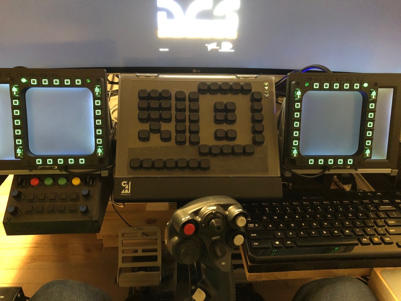
MBB v01 in the bottom left.
I am not fast at this. I am not slow, according to some definitions of slow, but I am certainly not fast. ![]() I am going to take a moment to pull everything together and go through the process so that in case it helps others but first I want to give a huge shout-out to @Troll who was patient and helpful throughout the whole process. Without him this would have been a longer process and I would likely not have finished. Any likes attached to this post go his way.
I am going to take a moment to pull everything together and go through the process so that in case it helps others but first I want to give a huge shout-out to @Troll who was patient and helpful throughout the whole process. Without him this would have been a longer process and I would likely not have finished. Any likes attached to this post go his way.
The Genesis of an Idea
It always starts with an idea.
After a good friend of mine (thanks Danny!) received his Prusa Mk3 3D Printer, I felt the inspiration to start down the path to building my own USB device. I had been throwing ideas around in my head for 20+ years. It started with Falcon 4 and wanting to make my own MFD devices but thanks to Thrustmaster and CH Products making devices that could do what I wanted, I didn’t have to those. I never stopped thinking about it, running through design ideas like a mental exercise.
I had been flying around in the DCS M2000C by RazBam and struggled to deal with the radios. I, somehow, didn’t have enough buttons in front of me to adequately map the radio device functions and using the mouse to hit them while trying to fly the virtual aircraft was am exercise in frustration. In the Mirage they are located a little forward on the left and they can be a little tedious to access with a right handed mouse while trying to fly with my left hand on the stick.
Enter the 3D Printer + @Troll’s custom hardware posts. Inspiration arrived.
The Early Design
To start off you have to imagine your way through a couple of design problems. These problems need to be though about early, because they will set the basis for the rest of the design:
- What does the design accomplish - its functionality;
- What does this design look like, overall;
- What pieces and parts does it consist of;
All three of these are fairly critical early on because, together, they will give you the starting points for the size and dimensions of the design.
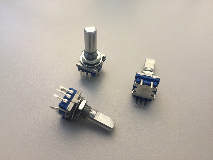
I wanted a panel that I could devote to communications for various modules in DCS and X-Plane. It could even double as a navigation panel in a pinch. I wanted a panel that could attach to my desk, hanging under it and sitting forward to be within easy reach. I wanted a panel with a set of rotary encoders, a couple of toggle switches and some pushbuttons that could act as up/down actions for the radio thumb-wheel encoders (that I could not find anywhere I looked). I wanted a panel that could do that in a relatively small space, right above my left knee in my cockpit layout.
These little chaps where the beginning.

The Layout
As Adam Savage always states: “Failure is always an option”. That is true in literally every project and you need to embrace it. It is the fundamental way we learn. What you want to do is fail early and fail often. That’s going to allow you to adapt and think through your problems quickly and cheaply.
To tackle the layout problem, after I had ordered some parts, and disassembled a few boxes to allow we to prototype the design. This was simple and let me hold and handle the parts and layout in the real world.
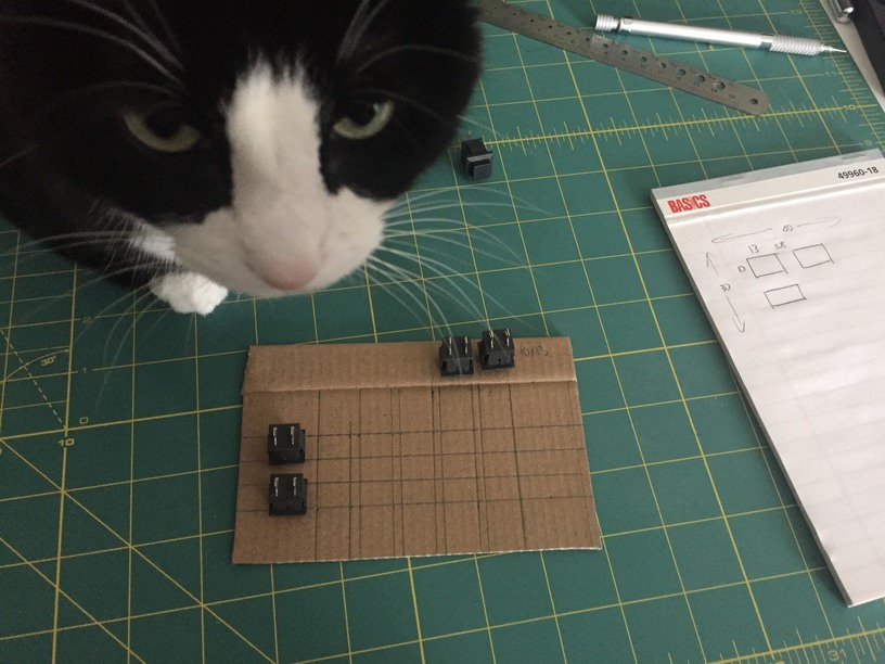
It let me see some of the challenges that I was about to face and let me make mistakes when measuring that I would carry forward.

It let me place the design and figure out where it is going to live. It let me teset the design early without having to commit to a box and having to ‘destroy’ that box to learn from my early mistakes.
It let me check to see if the left side is where I actually wanted it, or if it could go on top of the desk, or anywhere else. The above picture is on the right side (above my right knee) but this is where I have my keyboard and there was no where else that the keyboard could exist.
The Box
This is where I spent the majority of the year - designing and redesigning the box. It became a time sink in that I was always improving the design, changing how I approached and solved the problem.
I started with the front panel - which went through more redesigns that I can accurately describe. I made a ton of mistakes here, which was not as frustrating as it may sound because it gave me an excuse to go back to the drawing board and try it again. ![]()

While iterating through those designs, I was also tackling the problem of how to mount the switch panel to the desk. I started by measuring the profile of the desk (and the structure that sits underneath my desk), turned that profile into a 3D print and added some simple bars to allow me to check the fit.

The most complicated part of this whole project is right there in those few pictures. Take a switch panel and design a holder for it, rotate it at a weird angle that ‘felt’ right but wasn’t intuitive and spend the rest of the project struggling to manage that relationship. This is the part where I would tell past me to make this simpler instead of spending hours and hours doing the following: rotate -27.5 degrees, move, rotate 27.5 degrees, check, rotate -27.5 degrees, move, rotate 27.0 degrees, check, rotate -27.5 degrees, move, rotate 27.12 degrees, check … arghhh! If only I had known that then ![]()
In addition to all of that, the switch panel had to be mountable to the front of the box. That meant that it needed a place that it could screw into. I ended up creating a bracket that would fit inside the ‘mouth’ of the box that switch panel could be screwed in to. And that had to match the rotation of the switch panel, yet sit far enough back from the panel to allow it to be somewhat recessed into the box.
I have a feeling that adding any angle to a project makes everything an order of magnitude more complicated. That is a lesson that I have taken from this project ![]()
That left me with the first beta box and panel:
![]()

It would get simpler, and more complex, that this as time went on.
After spending some time trying to print this on my friends 3D Printer and having some issues with the ABS version and thermal issues, I was feeling quite guilty in the time that I was taking up. These prints take hours and hours to complete and it was getting frustrating. I finally decided to bite the bullet and get a 3D Printer of my own, just so I could iterate through designs faster and with less guilt at taking someones tool and using it when they could be doing fun things with it ![]()
In order to get past the thermal warping issues I decided to split the box up into panels that I could glue together.
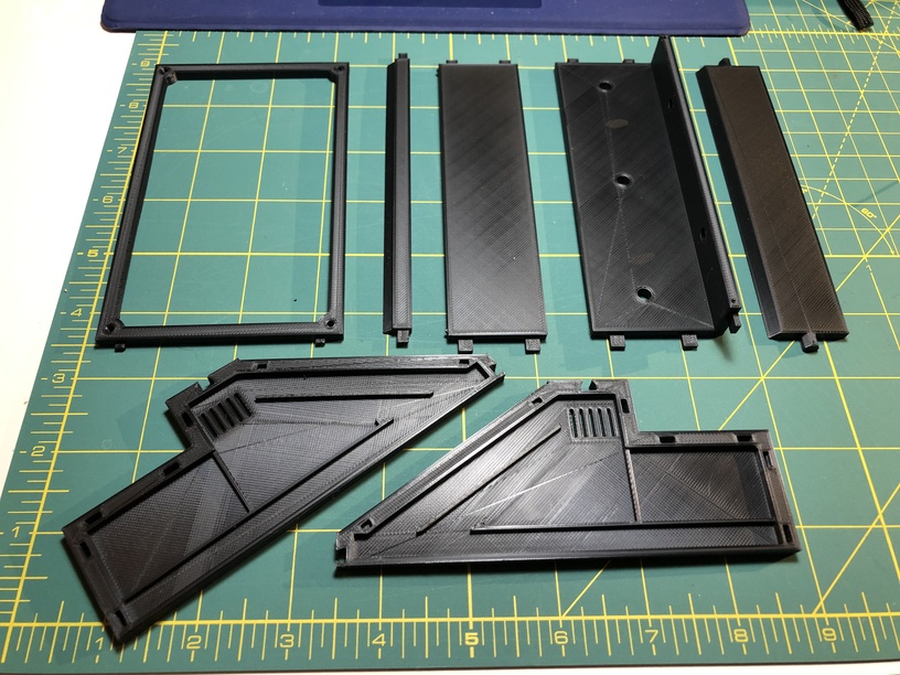
I also dropped my attempt to print this in ABS because I realized that there was no real point. PLA+ was good enough and easier to handle on the printer.
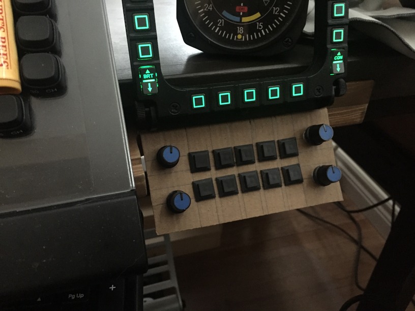
Here was the assembled, second to last version of the box:

And here is the box, test fit under my other desk to see if it ‘bends or warps’ as buttons are pressed - testing the wall width for structure and firmness:

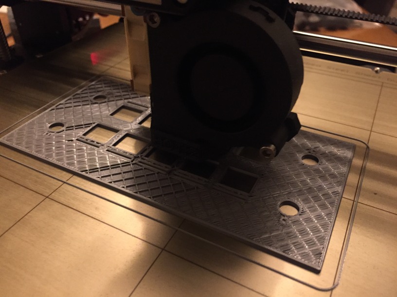
At this point I realized that I had another issue: the box wasn’t long enough. Since I had started this project, I had also started a project to put small LCD screens under my Thrustmaster MFDs. That pushed the MFDs out from the front of the desk by a few centimetres, meaning that the button box was going to see too far back, underneath the MFDs and the top row of buttons was going to be unreachable. If you refer to the first picture in this post, you can see how the extended length of the box allowed the buttons to just become visible, and useful, without putting them too far forward and causing the box to move/bend/warp when the buttons are pressed.
By splitting the box up into panels I had, inadvertently, made it easier to fix this problem - only having to rebuild a few pieces of the box instead of the entire thing.
One thing that I have not touched on yet is the bottom of the box. It needed to hold the electronics and be detachable from the bottom for ‘maintenance’ and assembly. Given the experience with the switch panel above, this a simpler problem to manage as it could be a simple plate with stand-offs to mount the PCBs to.

If you would like to take a look at the 3D opbects on TinkerCad, here are the links:
| Group Name | Link |
|---|---|
| Profile | 3D design Profile V1.1 - Tinkercad |
| Cross Beams | 3D design Cross Beams V1.1 - Tinkercad |
| Bottom Plate | 3D design Bottom Plate V1.1 - Troll_01 - Tinkercad |
| Switch Panel | 3D design Switch Panel V1 - Tinkercad |
| Switch Panel Cross Beam | 3D design Switch Panel Attachment Cross Beam V1 - Tinkercad |
The Switches, Interfacing with the Teensy and MMJoy
Before I wanted to tackle the wiring, I wanted to understand how the system was going to work from an electrical-to-software standpoint. I wanted to figure out what challenges that I would have to handle on the software side before I had implemented a wiring pattern that I might seriously regret later.
The first switch that I wanted to look at was the more complicated of the switches: the rotary encoder. Other momentary pushbuttons seemed fairly straightforward but that one might give trouble. I wired up a test to take a look at how the switch responded.
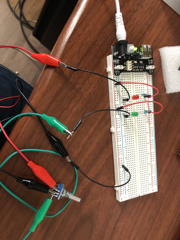
And that was … weird. I expected it to be simpler and act as a push button in each direction but it was more complicated than that - because the mechanics of the switch need to handle rotating in either direction. What happened when you turn the switch through one ‘tick’ (the physical barrier you feel when you turn the switch (so there are 20 ticks around a full 360 degree turn of the switch)) is that both lights would flash. What? Yeah, both. But if you slow it down and mechanically move it into, through and out of the tick, you can see what happened - it generated a ‘pulse’ as you enter the position and a ‘pulse’ when you come off the position. If you rotated the switch really slow, then you could hold it as it was part way through one of those ticks and you saw this.
Counter-Clockwise
| Descrition | Green | Red |
|---|---|---|
| neutral (resting position between ticks) | No | No |
| Entering the tick | Yes | No |
| Fulling in the middle of the tick | Yes | Yes |
| Leaving the tick | No | Yes |
| Neutral | No | No |
So as you entered the tick, one led would flash and as you left the tick the other one would flash. And that caused me to panic because how the heck do yo solve that in hardware?
Ah but this had been done before and there are software solutions to handle just this:

@Troll pointed out that MMJoy does this for you. Excellent. Lets go through that setup then ![]()
Initial Setup of Teensy 2
- Install Arduino IDE: link;
a. f:\Projects\Teensy\Arduino; - Install Teensyduino: link;
- Use Teensy software to load Blink: tutorial;
a. F:\Projects\Teensy\Arduino\hardware\tools\teensy.exe;
MMJoy Firmware
- Download the ‘Firmware Archive’ from here: link;
- Extract to a project area: Ex: F:\Projects\MBB-v01;
- Run MMJoySetup.exe (F:\Projects\MBB-v01\MMJoy2\MMJoySetup.exe);
a. Connected the Teensy to the USB port;
b. Press the Teensy Load/Reset button;
c. (1) Select VID PID0478 from the Device List;
d. (2) Select the Firmware Tab;
e. (3) Select Chip: atmega32u4;
f. (4) Select Bootloader Type: Teensy2;
g. (5) Select Firrmare File: F:\Projects\MBB-v01\MMJoy2\Firmware\Firmware_lufa_[MMJOY2.ATMEGA32U4].hex;
h. (6) Select Upload firmware button;
i. Verify that the device changes to MMJoy2 (MMJoy2-20151118);


Test the Teensy Config with a Simple Button
- Run MMJoySetup.exe (F:\Projects\MBB-v01\MMJoy2\MMJoySetup.exe);
- Hook up some hardware (this is not an optimal layout
 ):
):
a. (1) D3 on the Teensy2 to one side of the switch;
b. (2) Diode on the ‘exit’ of the switch;
c. (3) Diode to D2 on the Teensy2;
- In MMJoy2:
a. (1) Select the device (MMJoy2);
b. (2) Set Rows: D2;
c. (3) Set Columns: D3;
d. (4) Set Button 1 to Hardware Button 1;
e. (5) Set Mode to Switch;
f. Bush your button and look for this:


Test the Teensy Config with a Complex Button (Encoder)
This rotary encoder (not sure if that is the correct name as it often returns different result from Google searches - may be called a mechanical encoder) turns clockwise, counter-clockwise and has a push-button action when a force is applied downwards on the shaft. Mouser.ca link t a similar device: here.
-
Run MMJoySetup.exe (F:\Projects\MBB-v01\MMJoy2\MMJoySetup.exe);
-
Hook up some hardware (this is not an optimal layout
):
a. (1) D3 on the Teensy2 will be column;
b. (2) D2 will be Row 1;
c. (3) D1 will be Row 2;
d. (4) and D0 will be Row 3;
e. The column breakout at (1) feeds the inputs of the encoder;
f. Output (2) comes from the push-button action;
g. Output (3) comes from the counter-clockwise rotation action;
h. Output (4) comes from the clockwise rotation action; -
In MMJoy2:
a. (1) Select the device (MMJoy2);
b. (2) Set Rows: D2, D1 and D0;
c. (3) Set Columns: D3;
d. (4) Set Button 1 to Hardware Button 1. Set Mode to Switch On (provide a signal when the switch is activated (where as Switch Off means provide a signal when the switch is deactivated);
e. (5) Set Button 02 as an Encoder input;
f. (6) Set Button 03 as an Encoder input;
g. (7) Not sure if this is necessary but add a 50ms delay timer so that it does not spam the outputs (as I understand it, the Teensy will cache some number of inputs as fast as you can send them and this delays sending them out on the USB bus);
h. (8) Add hardware Button 02 to Joystick Button 2;
i. (9) Add hardware Button 03 to Joystick Button 3;
j. (10) Send the config to the Teensy device (save it on the device); -
Test with the VKB Button Tester;
a. Along the bottom of the MMJoy2 app, select the VKB Button Tester button to launch the app;
b. (1) Select the MMJoy2 device;
c. (2) Make sure that the Show log checkbox is selected.
d. (3) If it was and there were a bunch of buttons spammed from another device before you switched, you can use your mouse to select everything in this box and hit backspace to delete it;
e. (4) Press your buttons and check for the results in the (3) log - in my case the button presses occur to fast for the VKB app to flash the corresponding light and this caused me to think that things were not working for some time. Once the log was enabled, you can accurately see with is being sent from the Teensy device.


Success!
The Electronics
@Troll was kind enough to send me a Teensy board mounted to a shift register board that be had built with an additional 2 expansion shift register boards. I originally anticipated using something like the blank PCB above but the boards provided by @Troll meant that I could focus my time on other things and, in the end the project did not spiral down into a long, drawn out attempt to recreate those boards with solder, wires and elbow grease. I think that I spent so much time with the 3D print design that I was, unconsciously avoiding getting to that phase of the project.
Looking back on it, I underestimated the time that would have been required to do the electronics without those boards. I would argue that the box design would have had to change as well to be able to incorporate enough space for me to do what those 3 boards to so efficiently.
Yeah. I don’t want to go there. ![]()
On the electrical side, the first task was ti figure out how I was going to wire up all of those switches to the pins on the PCBs.
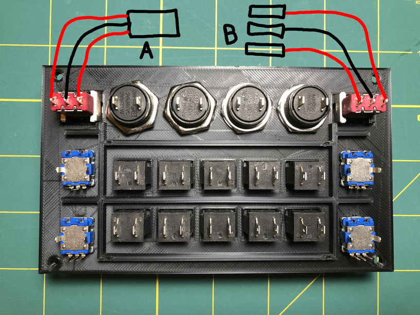
I could mount them directly, using option B above - which meant that they each had to have Dupont connectors on each of the wires. Or I could mount them in sets to a ‘break out’ board that would ‘map’ to the PCBs, option A.
This is how Option B would have looked from the PCB perspective:

It would mean ‘less work’ but ‘more chaos’ inside the box and I think that troubleshooting would have been a nightmare. Option A it is.
I started out by creating cables to attach the expansion shift register boards with the main board. Mounting the Dupont connectors takes practice and over the first 10-15 I had to develop a technique to get them on there with a low failure count:

After that, I felt confident and moved on to the cables that would attach the shift register inputs to the breakout PCB:
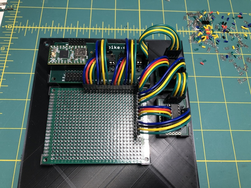

It is hard to see but in that previous picture you can make out where (some of) the switches would connect (in the glare area to the upper right of the PCB).
Underneath, it looked like this:

Shift register inputs along the left and bottom of that previous picture with some of the switch inputs on the right and how they are ‘mapped’. Note the common ground along the far right column of switch inputs. Colours were chosen to allow for relatively easy tracing if there was a problem.
I did not take a picture of the completed breakout board and I really which that I did, but I think that you get the idea. Along the open space at the bottom right of the previous picture, all of the ‘three position’ switched had their inputs mounted - with a common ground.
Next, it was on to the switches themselves:

Let loose the Wire Kraken!
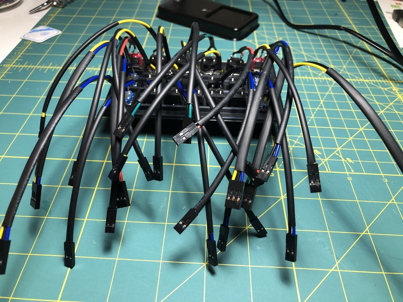

If you are astute you are now starting to question a design decision that I had failed to take into account from the beginning: How in the heck are all of those wires supposed to fit in the mouth of the box??? I did not take into account the space needed inside the box to accommodate all of that wiring!
I managed to connect it all up:
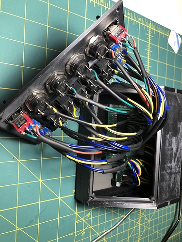
But the picture does not do it justice. That is one tight space. I managed to get it closed and I left it for a day to see if anything would ‘pop’.

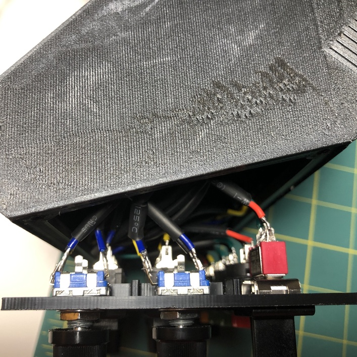
And after a day, everything seemed to be stable - no wires had torn themselves free and the screws did not pop free from the pressure on the panels.I did remove the panel and changing the heat-shrink on the rotary encoders to prevent them from shorting out, which you can see in the previous picture is a distinct possibility.

The After Action Report
After attaching the whole thing to my PC and screwing the box into it’s permanent position in my cockpit setup (after having to take it all apart again to attach it to the desk), I went in to MMJoy and completed the mapping.

And it is working beyond my expectations! In DCS I have every button mapped to a function in the F/A-18C and it works beautifully! I full expect it to start to fail at some point, as I am somewhat concerned about the pressure that was exerted on the wiring to get it all in place, but for the past month it has worked with no issues!

Again, I can’t thank @Troll enough. His patient help with the wiring and MMJoy and providing the main board and expansion boards was invaluable! The amount of time saved, let alone the potential frustration in trying to wire something like that up on my own, was monumental!