In anticipation for the upcoming release of the OH-58D Kiowa Warrior for DCS…
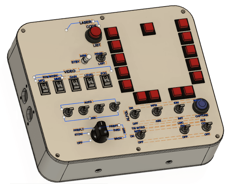
I designed this panel for the OH-58D (as I have nothing better to do whilst I wait impatiently), for this purpose i re-used the virpil panel as a template, but if you’re doing a DIY panel you could use any suitably sized electrical switch panel…
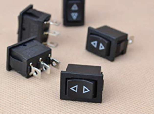
please note: the small rocker swtiches will be 3 position mini rocker switches,
not the on/off switches modelled above (which were acquired from grabCAD in haste)
also - I use a face hugger so I do not need a working MFD screen for VR
However if you were so inclined you could utilise a cougar MFD and one of the small LED screens from aliexpress to build a working unit, or if you didn’t want to use a TM cougar, you could just place momentary push button switches (as modelled above) but spaced out around the perimeter of your screen.
Limitations would be screen sizes available & or panel size availability also.
I hope this gets some people thinking about what other treasures we can create for the little gem thats coming… (cannot wait!).
i knew I had another pic somewhere.
this had the swtich label texts
unlike solid works though I was struggling to work out how to etch the labels in with fusion360…
i must admit @smokinhole, it is nice to come to a forum where its members are providing positive and constructive feedback, rather than the normal vitriol and diatribe whilst flaming each other over minor differences of opinion. And coming from @Troll (unfortunate name) who has made some incredible contributions to the site and helped me out every time I’ve needed assistance/guidance - I’ll take what i can get.
It’s all @TheAlmightySnark 's fault anyway, he pointed me in the direction of this forum …
just an FYI, for all my electronic panels I utilise these arduino clone pro-micro ATmega32U4 cards from aliexpress that are dirt cheap and can be firmware flashed to run MMJoy2 along with some shift register 74HC165 development boards to make multiple switch connectivity and configuration super easy
Here is a little speel I did explaining the benefits of shift register over switch matrix in laymans terms (words that even I could understand)
for the new comers amongst us who may not want to ask the basic questions https://avimator.net/229wiki/index.php?title=Shift_Register
The fact that you can daisy chain shift registers, and consequently a lot of others chips is probably one of the greatest inventions of the modern world!
I was trying to build a PCB specifically to make the wiring nightmare easy for myself
it wasnt until I approached a mate (Virtualinsanity) who used to solder SMD for a living and is a electronics wizard & set me straight.
Thanks for the explanation of the shift register board. Very clear and understandable!
I’m building a JF-17 pit soon, that will cut down my usb inputs alot!
I guess since it runs on MMjoy I need a seperate arduino for powering my backlighting and those LED’s I need for indicators?
hey @Lobinjaevel, thanks for the feedback on the write-up, I havent done any arduino coding, as I’ve been limited to making (joystick) controllers with axis (my DIY pedals) and the switch panels, as mentioned above, so MMJoy2 is a easy workaround for that, also I’m in VR so most of my stuff has zero cosmetic appeal (lighting etc).
I’m sure someone here would be able to help you out with the arduino code & working with DCS-BIOS. (both of which I have no experience with as yet).
You cannot use potentiometers with shift registers unless you would build a low res voltage divider in between, making a potentiometer pretty useless. Shift registers read either a 1 or a 0(0V or 5V/3.3V) relative to their reference voltage.
A potentiometer returns a unlimited range of value’s between the input voltage and the drain. A shift register would probably read a zero, a one or a quickly flipping value near the threshold between the other two.
A shift register can be hooked up to the digital ports on the arduino whereas the potentiometer would need the analogue ports.
There’s obviously chips you can buy that can convert(ADC/DAC) the value’s but the arduino has those built in. You could probably check out a controller board for potentiometers and see how that hooks up!
OK…let us all be honest…when you when you saw the first screenshot, raise your hand if you looked for a convertible with an amorous couple in the back…