Correct.
The side with the two pins is the push button function.
The three pin side is common/gnd in the middle, and the signal on the sides. I.e. Rotating one way closes and opens the connection between the middle pin and the pin on the side the axis rotate towards.
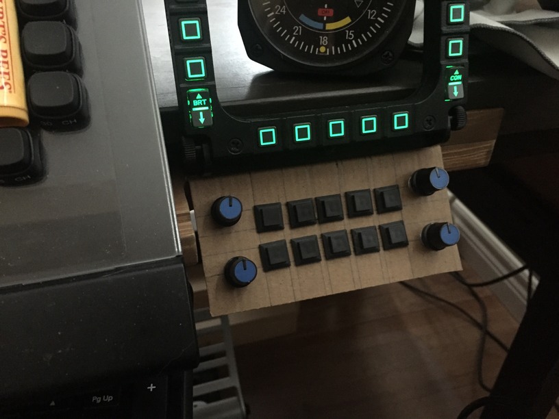
So here is the layout prototype for the face panel. It’s a simple little panel intended to hang under (attached to the desk under) my MFDs and provide a few rotary encoders and additional switches (so I don’t have to hunt and peck with the mouse to change frequencies). Plan is to use this prototype to do up a 3d printed host box for it un my friends 3D printer.

Here is what it looks like on the left:

And here is what it looks like on the right:
Originally I was considering just the one box but now I am thinking two might be cool. I should be able to use just the single Teensy processor for both. I think.
I ordered a Teensy 2 board and a small Arduino starter kit that came with a switch register (think that is what it is called, my mind is telling me that’s the wrong name but I doubt my doubts ![]() ).
).
And for anyone interested, here are two from making the prototype:
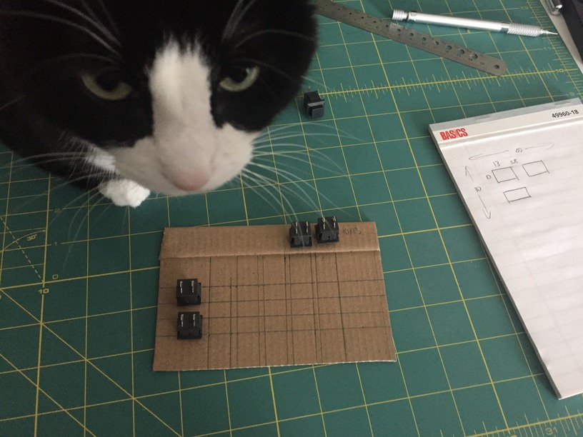

Cat kept going for the knife. You know cats.
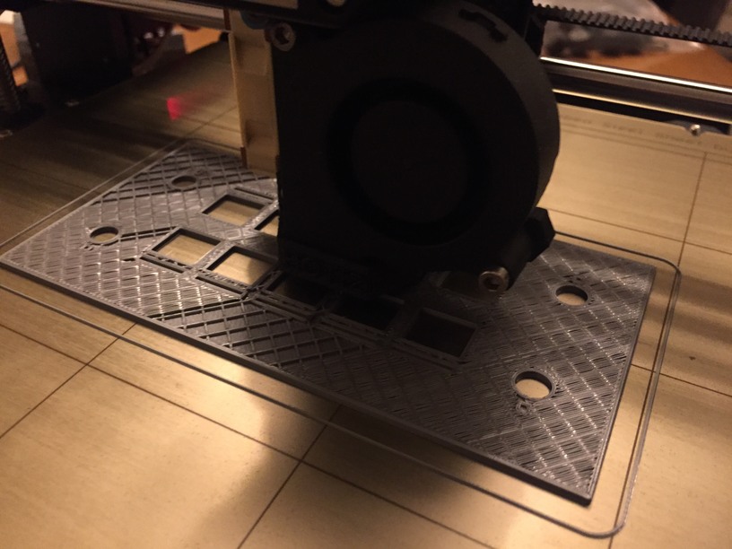
Did a little 3D Printer work over the weekend with the help of a friend of mine. He has a new Pursa I3 Mk3. With a calipers and about an hours worth of work in TinkerCad I was able to make up a template to test fit the design on my desk and lay out an initial attempt at the switch panel face. I managed to get both ‘somewhat reasonable’ though I had to modify the sizes of the holes to properly accept the switches (another 30 minutes of TinkerCad work).
Here is a couple of camera phone shots of the printer working it’s magic on the front panel:

So, above I mentioned the profile piece I prototyped and printed. When I confirmed that it fit the desk as expected, I doubled them up in TinkerCad and added some ‘cross beams’ to put them the proper distance apart. I cut a piece out of each of the sloped beams, where the panel would, if I measured everything okay, slot in.

It was 2am when I finally made it home. I could not resist pulling all the switches from my earlier template and fitting them into the panel.

View from the front. The panel with the switches installed is the 3rd print. The second print is below it and the initial prototype is off to the right. The 2nd print had a curling problem on one corner, so we did a third after increasing the bed temperature and cutting the model up into more, thinner Z-slices.

If you look at the 2nd print (bottom) you will see little cut-outs above and below the switch positions. My thinking was to have a small, thin layer on the bottom (the front of the panel), with a void behind it with a series of LEDs inside the box. The thin layer of the print in those voids allows the light to shine through. After the printer is upgraded with the multi-filament I plan on replacing these voids with clear material and pushing them through to the surface. It might make a neat effect ![]()
Here is the switch panel sitting in the cutout section of the desk template. If fit exactly as I had hoped ![]()

I spent a couple of hours in TinkerCad today tuning up the switch panel and filling out most of the desk box as best I could. I have to put in some screw holes and something for the screws to screw into and decide on the final height of the box.

Next step is to pause the box design and wait until I have some idea if the electronics will fit or if I need to increase the height of the whole thing to accommodate.
I ended up getting a Teensy LC board instead of my planned Teensy 2 board (so I could make use of @Troll’s knowledge with his A DIY Radar Controller - #80 by Troll experience). But, goes to show, researching the Teensy first would have let me know that the boards are not pin-compatible. That’s okay for my next step, prototyping the electronics on a breadboard, but it means I am going to have more questions ![]()
I expect that the next phase is going to take some additional time to work through. Before I start, though, I have a couple of questions for people in the electronics know. I have a Saitek Throttle Quadrant that died on me a year and a half ago. It created problems whenever it was connected to the USB port on my PC. So, I pulled it apart ![]()
What I am wondering is: how hard would it be for me to hook up the axis devices, in their shell, to the Teensy and pass them on as axis inputs?

Basically, I am considering putting them back into their enclosure and running the wires into the Teensy controller and wiring them in as 3 axis analog inputs. Does this make sense? What are the wires above (Red = power, Black = ground, Yello = ?)?
In the next picture, what is the C23/C24 component on the board? Capacitors?

Regarding the Saitek throtle quadrant.
I know a guy who is doing various conversions to halls with original electronics or diferent one.
His page with many useful info. I guess he speaks english so maybe you can ask him for specific details if needed:
Red +5V
Black GND or -
Yellow Signal
Lick the red wire…
Only now caught up to this thread. The forum gets busier every year!
Really cool project: with all the HOTAS and MFD hardware, a radio panel is the next logical step for a universal controller for all aircraft.
Also, that is a very cute cat! I involuntarily made a sound when that head popped up between the hardware.
An update. 3D Printing, although miraculous, can be a pain in the arse. I have been experiencing issues getting the main box part built due to the support structure needed.
![]()
Problem 1: If you take a look at the image above, the two horizontal parts (and the virtical part that connects them) are requiring support structures underneath in order to print. that strucutre is resulting in a very rough surface and it is proving difficult to remove that structure once the print has finished and cooled. It is driving me a little mad ![]()
Problem 2: Although the printer I have access to has a heated bed, but the time the print is finished at least one of the corners has significantly lifted itself off of the bed. And it needs to be flat. Grrr. I think that my friend who owns the printer needs to build an enclosure to keep the print ‘temperature stable’ but that is proving to he a hard idea to sell;
Problem 3: I started with PLA for the prototype and switched to ABS for the final. I didn’t realize it, but it makes sense now, that the change in material requires a change in printer settings and this has been an adventure in dealing with the technical details of the material.
Since we (my friend and I) are printing things at a rate of about 1 every 2-3 weeks, it has been a slow process to get the last pieces printed. I am tempted to try something like shapeways but I am not sure what their support structure would look like under/inside the model above. That being said, I am using up a lot of plastic to figure all of this out so it may be in my best interest to see what they can do with it.
An interesting problem to solve but, rest assured, I have not forgotten about this project! ![]()
Shapeways is about $110 US to print and ship the model.
We solved this by slowing down the print.
Yeah. We did the same but unfortunately for me, my friend lives in a drafty older house and refuses to turn the heat up :-). I’ll see if I can post a picture of the result.
Here we are. So the temperature of the house was about 18 degrees and started dropping about 2 hours into an estimated 10 hour build.

Side facing the viewer was facing an older window with and a wall would have been along the right (which my friend reports as prone to drafts.

This is the corner that is in shadow in the picture above this one. The front displays a similar curve but a little less pronounced.