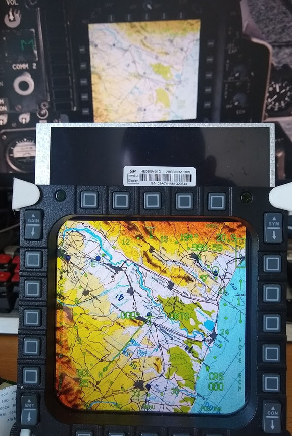
I have been working on a little adjustment to my Cougar MFD’s, earlier this year I got my hands on 2 small displays to put behind the MFD’s and now that my 3D printer is on the way I figured it would be a good time to get started on combining all the components!
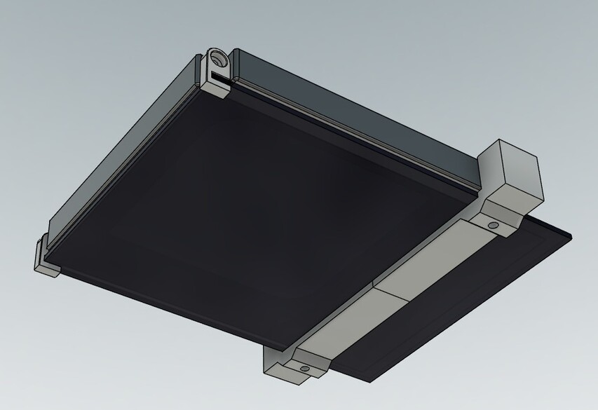
With the help of Fusion 360 and a bit of caliper work I got this:
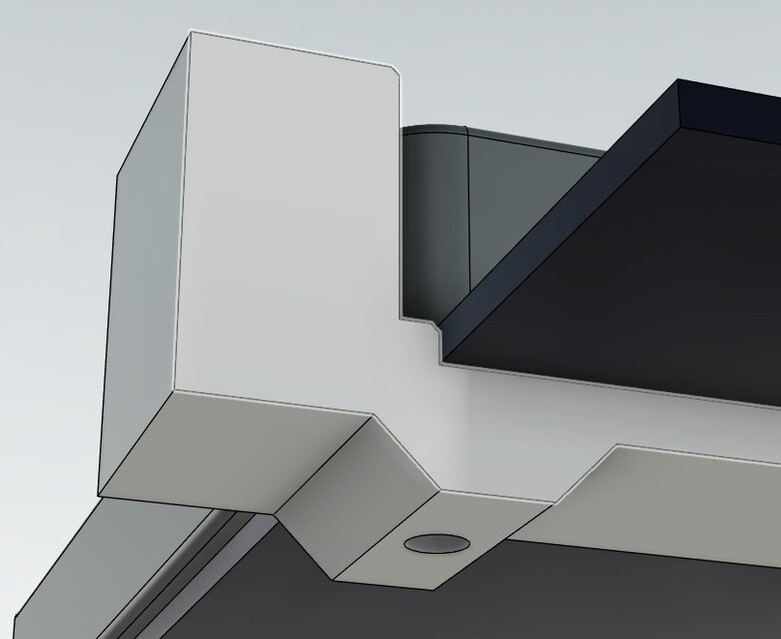
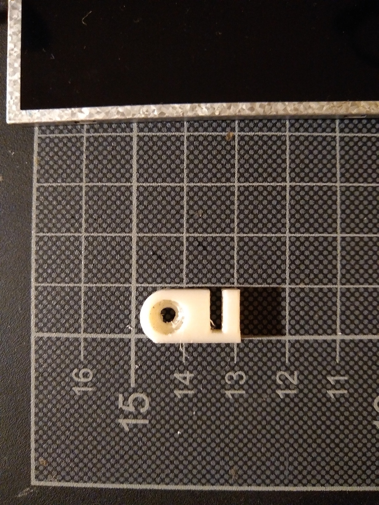
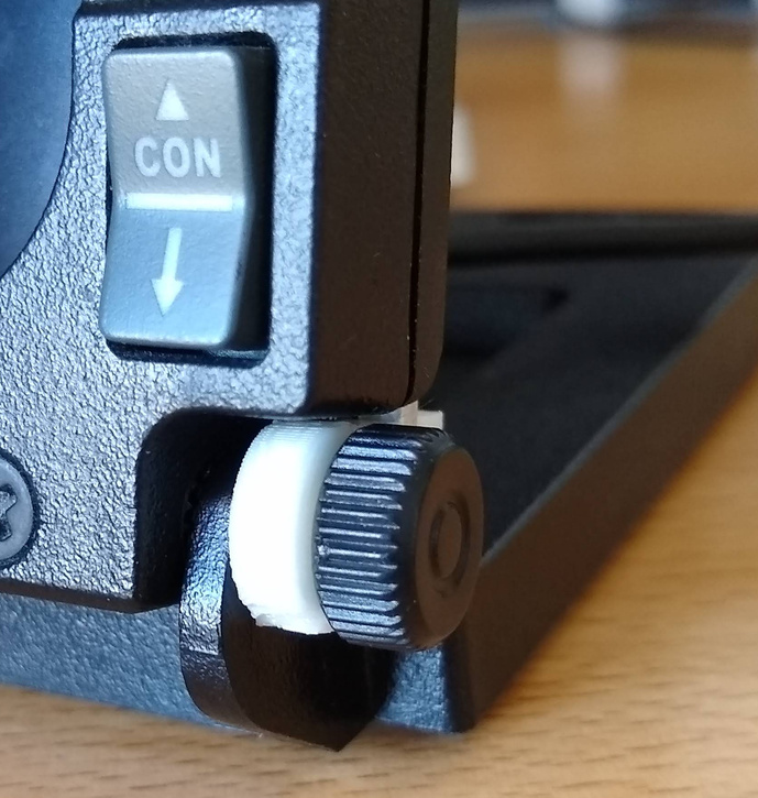
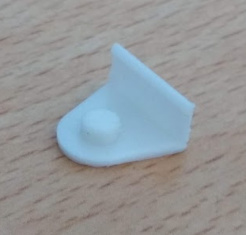
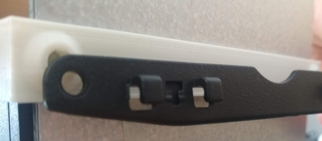
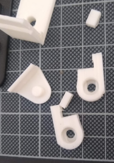
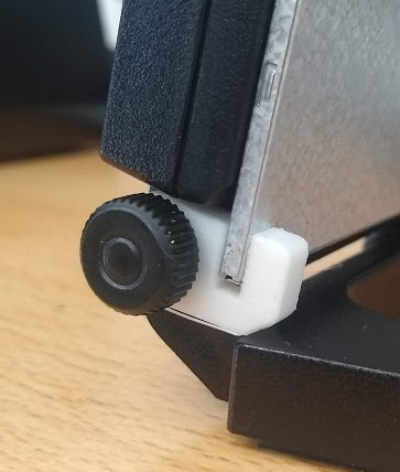
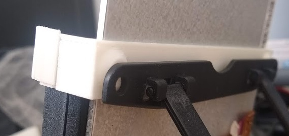
2 small white brackets to keep the display in place that fit on the existing bottom bracket connection of the MFD’s with the original bolt. On the top a beefy bracket to firmly keep the display in place and it has 2 stand-off that allow me to attach the original aft bracket that is used to regulate angle. The base is perfect since it’s already quite heavy and has a nice anti-slip surface.
A secondary goal was to waste as little of the original design as possible and I think that bit succeeded quite well. The top bracket does need one more bracket that fixates the MFD to the bracket.
Hopefully this is useful for anyone else out there, I am using two of these:
Though they vary a bit in price and there’s a lot of choice for displays. once it’s all working I’ll post up the original files in case anyone wants to replicate the results.
I have displays placed behind my MFDs as well … and never use them because DCS always reset the displays after an update. It’s not terribly hard to recover from this as DCS will usually back up the modified files before replacing them, but it is annoying
Fortunately this is easily solvable by using a .bat script to start up DCS, that forces a check for updates, and then recopies the modified display files back, and only then continues with starting DCS.
I can imagine! I just figured what the heck and went with these. Plenty of options to go by!
Yeah that’s not really going to happen, the displays act as any other display so it’s a DCS issue, other simulators can handle it fine and I haven’t seen much action on the dev’s on this bit unfortunately.
Another issue is the price of 1:1 ratio(square) displays, they are really only used by aviation companies so you got that tax if you want any… Then you end up with less subtle solutions like I am doing now. I’ve seen similar projects on hackaday and other such sites.
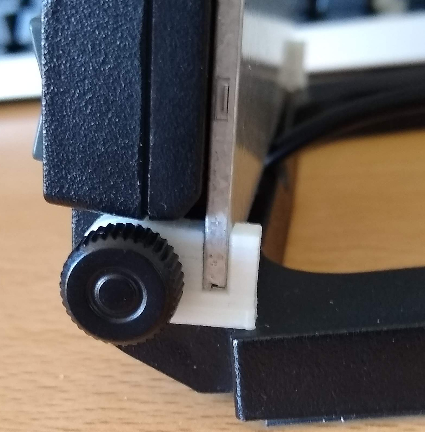
It’s not perfect yet, trying to nail down some proper settings for my printer but I am really enjoying the process of tinkering and experimenting! The screen fits really well so far!
I printed the holes on the back for the angle bracket a bit too big so alas, a reprint will be done. Will make the standoffs a notch bigger too, just so you can’t accidentally drive the parkers in your display!
The bottom brackets gave way. Mostly because I’ve let it carry the weight of the whole screen whilst I was moving it about and showing it off to people and well, this caused the 3D printed layer to gave way at exactly the point you’d expect.
I am pretty much working on a tiny scale because I’ve limited myself to reusing the existing hardware but it’s extremely enjoyable working and testing with materials like this and rapid prototyping.
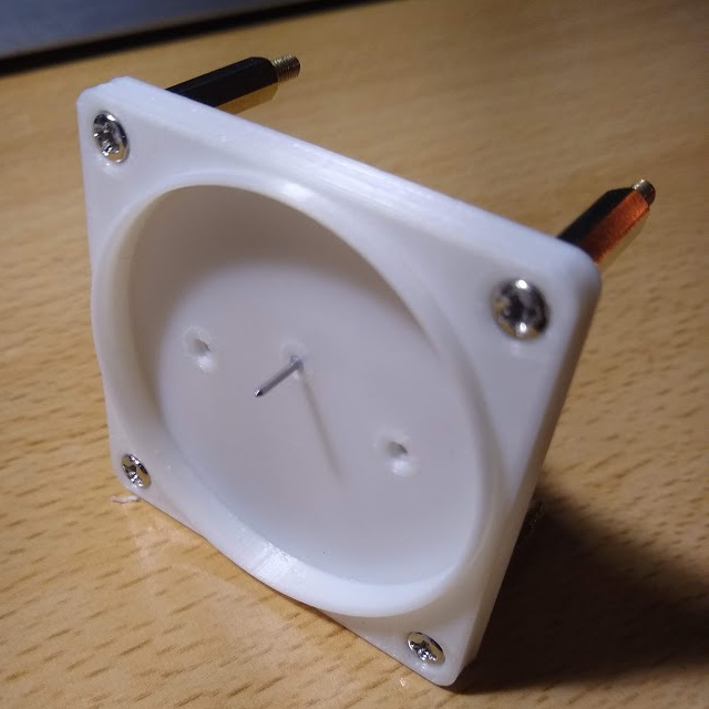
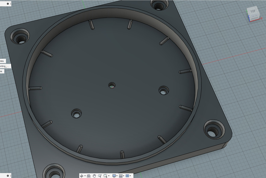
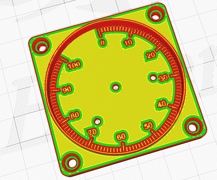
I have been refining the gauge design a little, properly fixed the steppemotor holes, added LED light slots and been working a little on a front plate with markings and such.
@Troll decided to go with Fusion360/Inkscape, 30 dollars for a single app is a bit much when I can pretty much punch in some numbers in Fusion and go with that. Same for Inkscape.
@Troll Any slicing tips? Using a custom profile for the Ender3 in Cura with a few experimental settings to hide the Z seam, reduce blobs and adaptive layers. Going to give it a go tomorrow.
Printed a Portal cube too, though I used Tree Support for the Bottom layer that is slightly inset so… that didn’t really work alas. Perhaps I will reprint it in 2 bits or just use some elbow grease.