That’s a good idea but unfortunately I do not have a colour printer currently.
1 Like
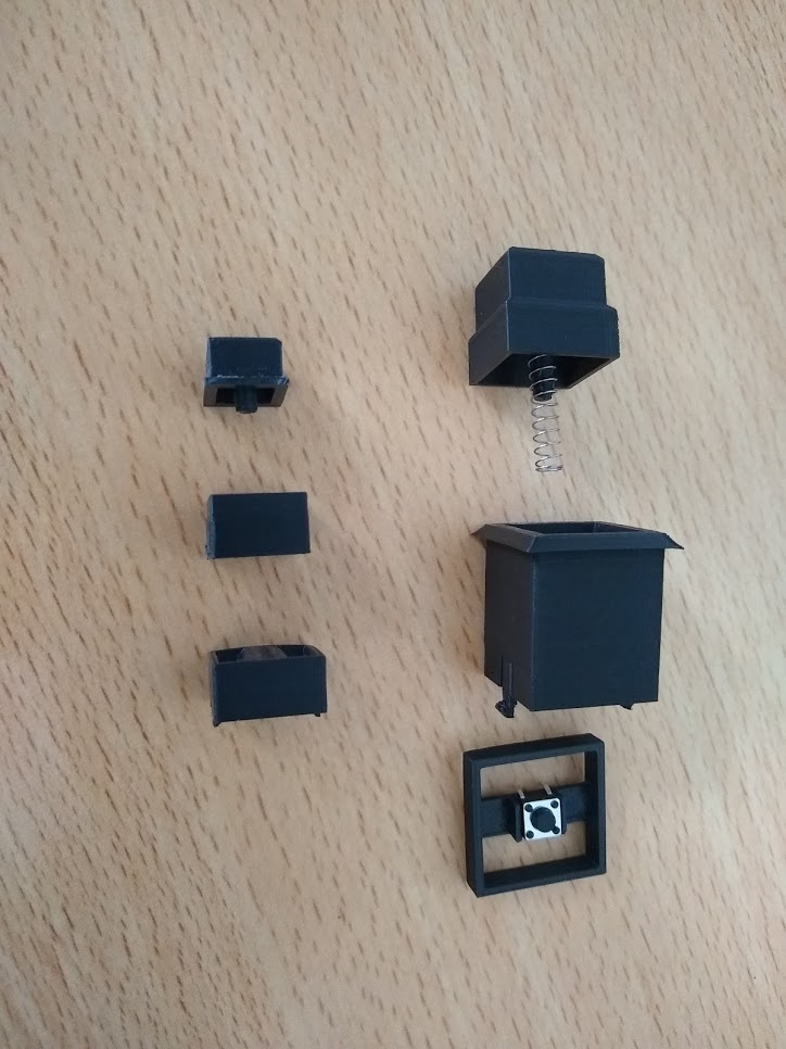
Had a fun day designing and building a button!
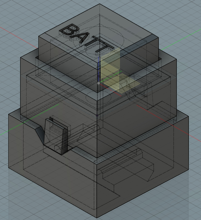
The button that moves up and down is 10x10mm, outside shell is 12mm. It still needs connectors so that it can mount in a panel though I’ve got half a mind to make the button size 12 or 15mm as a base.
I made the internal walls and the shroud at the base of the button the same size so it binds a little, so the prototype isn’t working smoothly.
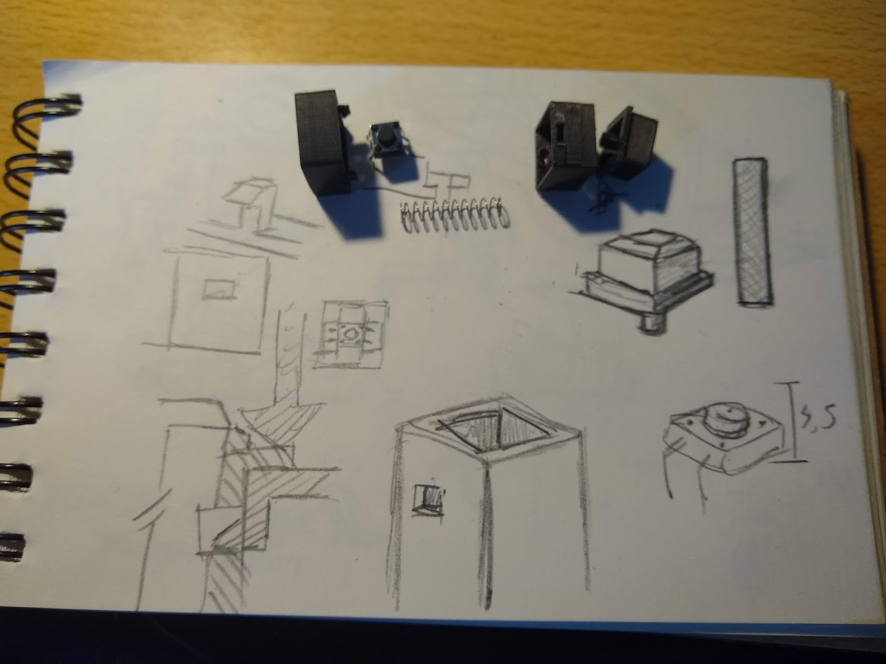
The button has a vertical pole on the inside with a chamfer, I can adjust this chamfer to change spring tension. The spring compresses quite a bit but that gives it a good feedback. At the bottom is a standard PCB mounted push button, both the button and springs are a dime a dozen and printing the whole assembly uses about 3 grams of material so quite a bit cheaper then going with off the shelf parts that do not have the dimensions or markings I would want!
4 Likes
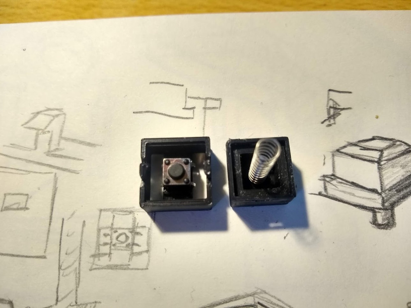
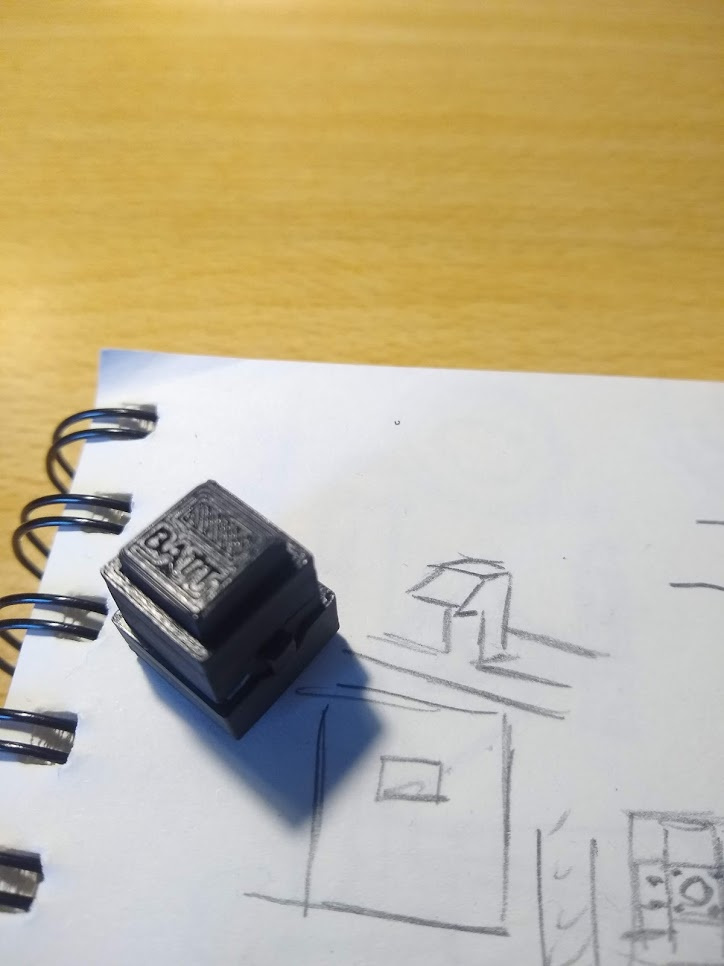
Prototype 2 on the right in this picture next to 1.It scales a lot better and will be easier to panel mount. I need to get some find gritted sand paper to smooth the sides, it is currently very ridge-y when you press the button.
Next version will have a little slot at the top surface and a LED internally.
5 Likes
It is inspiring to see all the creativity that 3D printing has unleashed within our Mudspike community. ![]()
Wheels
5 Likes
Been on a bit of binge learning FreeCAD in the past 2 months, mostly by doing a lot of the Model Mania challenges from solid works.
Anyway, since I print a lot of small parts I needed a better part cooling nozzle for the Ender 3. The original ‘nozzle’ is mostly just a small part that directs the airflow from the cooling fan into a 90 degree bend roughly towards the part. The airstream is as wide as the whole extruder unit including fans and such. I opted to extend it downward and create a smaller exit with 3 internal nozzles directing the airflow. Right now it hits the extruder at a nice height. This then directs the airflow downwards on the are that is received the most heat from the extruder nozzle.
3 Likes
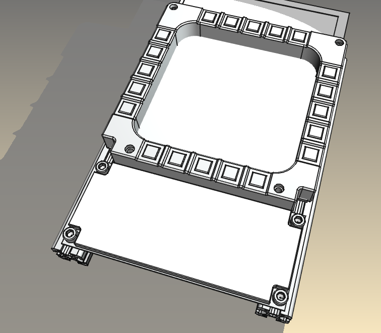
The last month has been one of… design. BUT ordered parts arrived! I have started building a frame out of 2020 extruded aluminium profiles that I can easily bolt stuff on.
This is the current focus, 2 sided obviously.
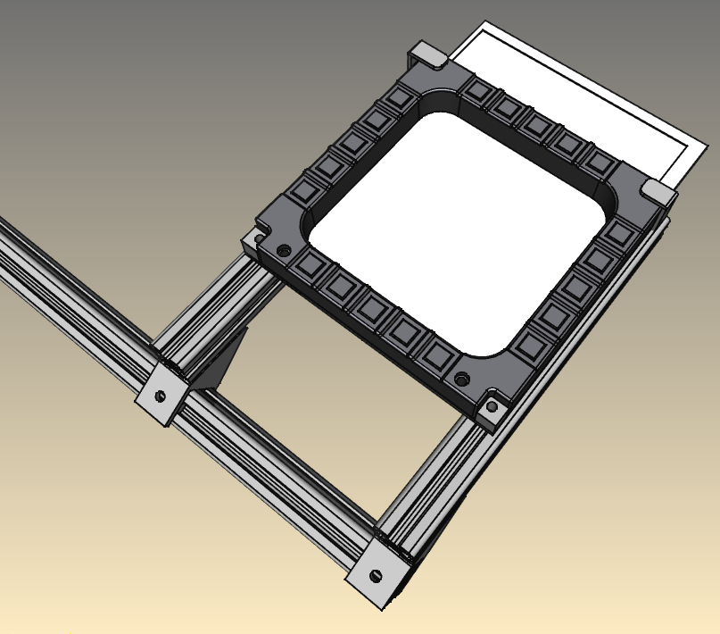
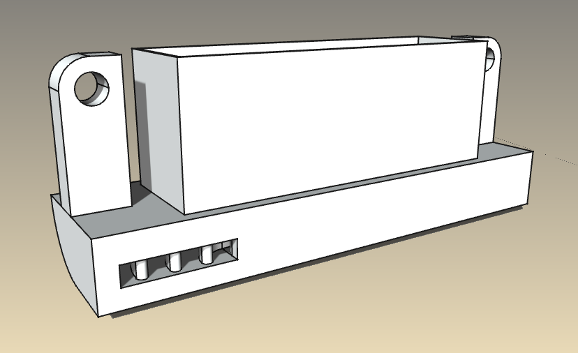
I designed a bracket that places the MFD’s with a display and some space at the bottom and top at a 60 degree angle. It will have 2 clamps, made to size that will keep it fixed to a desk, plus a vertical arm to affix extra panels and instruments plus a control stick.

I am now waiting for some simple M4/M5 bolts and T-nuts, normally I would go pick it up but everything is still closed. Oh well! The 3D printer has a happy time churning out parts now that I installed a BL touch sensor that makes levelling the bed a joy! It has become a lot more plug and play thanks to that.
This is an earlier version with a basic panel design that I can churn out at any size desired. putting holes and markings in it is a matter of minutes once I have made a choice.
KD-2-22 push buttons will form the basic input for a UFC that will come between the 2 MFD’s. The total assy width is about 50cm’s and so far expected costs are below 250 euro’s if you would need to buy all the parts loose. Though that does presume access to a 3D printer. The plan is to throw it all in a public Github repo and let people have fun with it once it’s all done.
4 Likes
Looking good there, @TheAlmightySnark!
Let me know if you need a third MFD frame. I have two that are collecting dust.
Pretty nifty little gadget, that one!
What firmware are you using for the printer?
1 Like
Thanks for the offer, for now I have plenty, perhaps when I figure out what to build next ![]()
I think Marlin 1.15? The install was pretty straight forward but the software was a PITA, Creality provided no direction what to install. I do have a Ender 3 Pro with a 8-bit board so it’s not the most recent that you can get.
1 Like
Got a replacement shifter for a MAN truck, printed an adapter for it(third attempt… whoops) and now to figure out a nice way to hook up the shifter as a game controller. I already have an Arduino for that that is capable of registering as a controller by default which is nice. The wiring is a bit trickier, not sure what I want to do with that yet… Best would be to create some sort of plug that can be hooked right into this side and into the arduino!
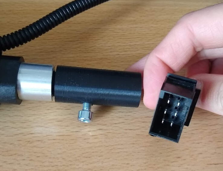
Oh yeah, it’ll be for my dad’s G27 steering wheel!
2 Likes
More! Show me more…
1 Like
@Troll not much more to show right now, figuring out electronics and such. once it is installed I’ll show you more!
1 Like
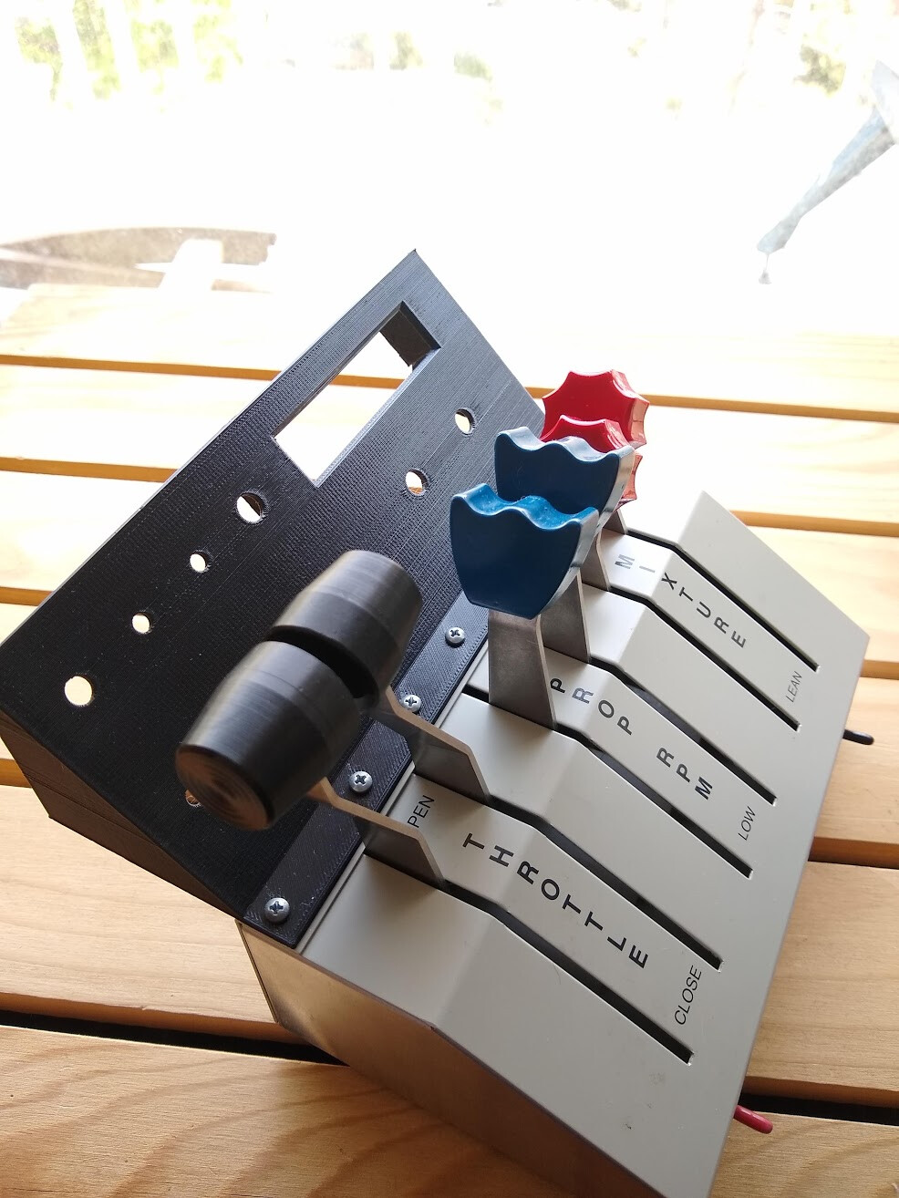
Working a bit on the throttle unit, upper part has been printed. The lower part will have to be printed on it’s own, mostly to cut down on timing(loose parts is 5 + 2.5 hours, as one is 10+ hours).
So far it fits good though I think it may be a mm or so closer to control levers then expected, I think I didn’t take everything into account when measuring. Oh well, live and learn!
4 Likes
I wouldn’t mind getting a look at the insides of that throttle… ![]()
4 Likes
My mind went…places…
1 Like
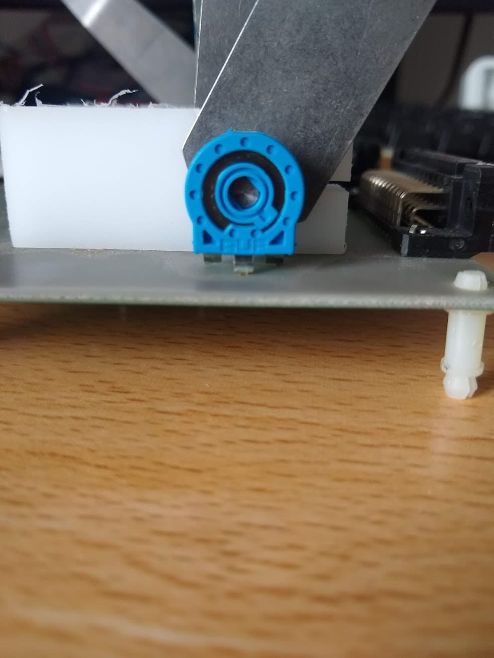
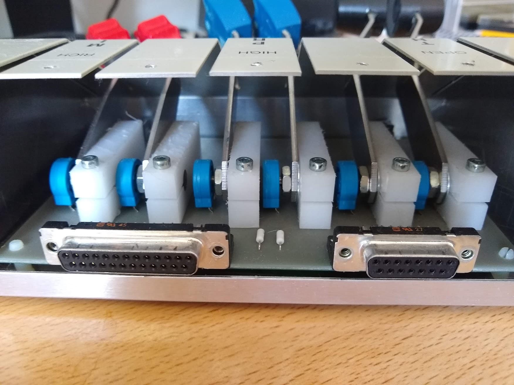
Side way view of the throttle sticks. You can see the potentiometers and the nylon blocks that clamp them down to provide friction. It’s a neat design! I don’t have a full top view currently but I’ll take one when I take it apart again soon.

This is the bottom PCB where I soldered in an extra line to provide positive power to the potentiometers.
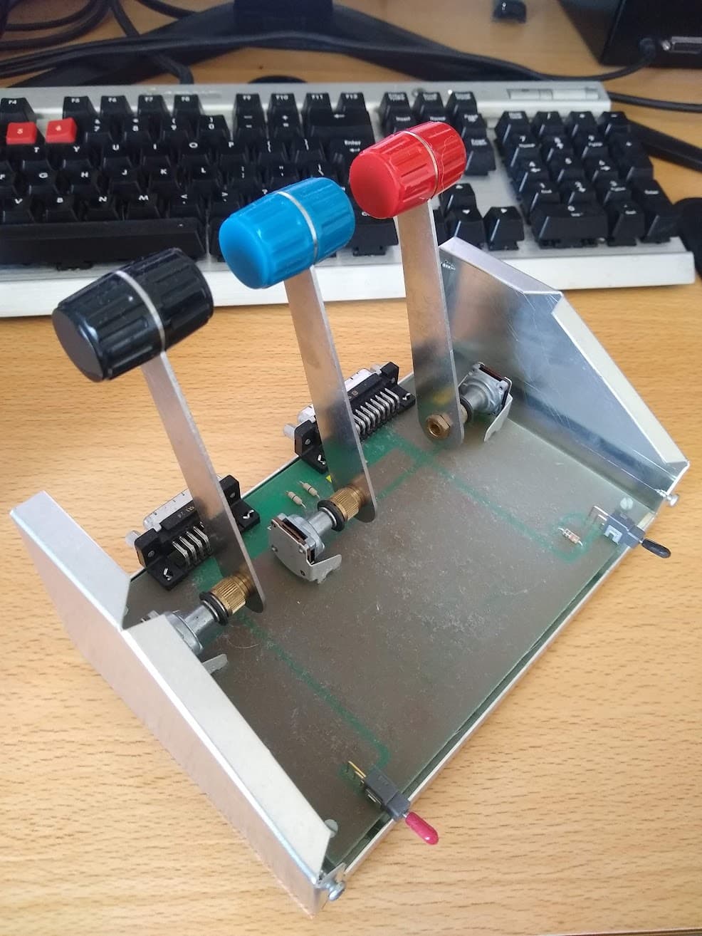
Yes, I have two units, here’s the 3 lever unit that has a different internal design. Oh and it is all weighted down by a beefy block of iron.
5 Likes
Surprisingly simple design! I expected something more complex… I guess the white plastic is some sort of low friction stuff, like delrin or similar?
Pretty sure they are just nylon blocks!
Yeah, nylon would work too.