Hello there.
I started this project to try and do a viggen cockpit ![]() gonna be interresting. Biggest peoblem will probably be the space needed haha. And after that will be learning to code.
gonna be interresting. Biggest peoblem will probably be the space needed haha. And after that will be learning to code.
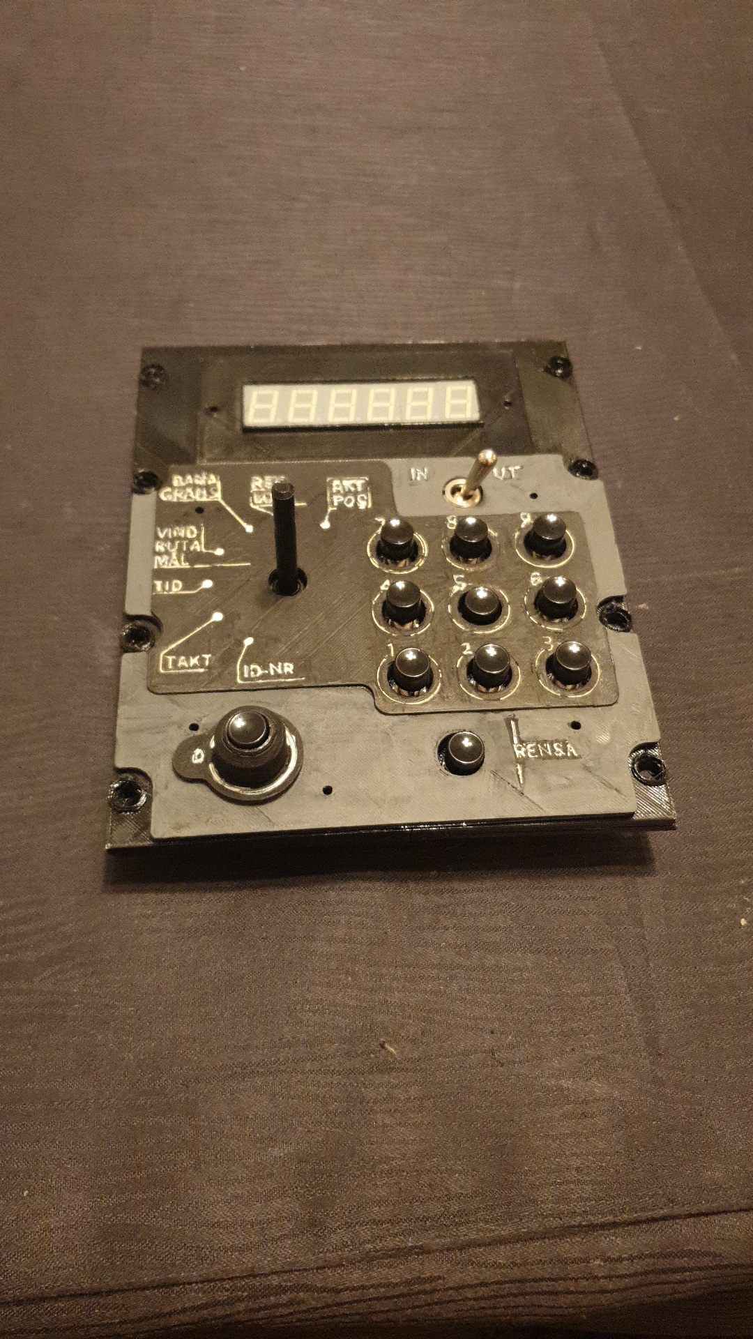
I have started with the nav/datapanel, it felt like a good start. There were already a topic created by Stingersharp over on (ED forum, Navpanel that had the dimensions. So thanks Stingersharp.
There are buttons, switches and knob and a display (which i am very very scared of xD).

Picture taken from Novelair, which is also where i bought the buttons for this project.
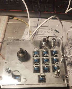
My prototype.
What kind of screws whould you guys use for the DZUS screws?
The switch was easy enough just on-off. That is one pin.
code was easy too.
#define DCSBIOS_DEFAULT_SERIAL
#include “DcsBios.h”
/* paste code snippets from the reference documentation here */
DcsBios::Switch2Pos dataInOut(“DATA_IN_OUT”, 12);void setup() {
DcsBios::setup();
}void loop() {
DcsBios::loop();
}
Then i did the buttons and was not so intrigued of using 11 pins on my micro so I made a matrix for that so only 7 pins were used for that ![]()
The code for that I got from Hansolo who hade done a matrix for the cdu on the a10, so thanks for that ![]() just altered it alittle bit.
just altered it alittle bit.
#define DCSBIOS_DEFAULT_SERIAL
#include <Keypad.h>
#include “DcsBios.h”
/* paste code snippets from the reference documentation here */
const byte ROWS = 3; //three rows
const byte COLS = 4; //four columns
char keys[ROWS][COLS] = {
{‘1’,‘4’,‘7’,‘A’},
{‘2’,‘5’,‘8’,‘0’},
{‘3’,‘6’,‘9’},};
byte rowPins[ROWS] = {0, 1, 2}; //connect to the row pinouts of the keypad
byte colPins[COLS] = {6, 5, 4, 3}; //connect to the column pinouts of the keypadKeypad keypad = Keypad( makeKeymap(keys), rowPins, colPins, ROWS, COLS );
void setup() {
DcsBios::setup();
keypad.addEventListener(keypadEvent); // Add an event listener.
keypad.setHoldTime(100); // Default is 1000mS
keypad.setDebounceTime(50); // Default is 50mS
}void loop() {
DcsBios::loop();
char key = keypad.getKey();
}void keypadEvent(KeypadEvent KEY){
switch (keypad.getState()) { // gives PRESSED, HOLD or RELEASED
case PRESSED: // If someone finds a better solution as switch - case: Let me know, please
switch(KEY) { // following commands are fired unique if PRESSED
//CDU
case ‘1’: sendDcsBiosMessage(“DATAPANEL_KEY_1”, “1”); break;
case ‘2’: sendDcsBiosMessage(“DATAPANEL_KEY_2”, “1”); break;
case ‘3’: sendDcsBiosMessage(“DATAPANEL_KEY_3”, “1”); break;
case ‘4’: sendDcsBiosMessage(“DATAPANEL_KEY_4”, “1”); break;
case ‘5’: sendDcsBiosMessage(“DATAPANEL_KEY_5”, “1”); break;
case ‘6’: sendDcsBiosMessage(“DATAPANEL_KEY_6”, “1”); break;
case ‘7’: sendDcsBiosMessage(“DATAPANEL_KEY_7”, “1”); break;
case ‘8’: sendDcsBiosMessage(“DATAPANEL_KEY_8”, “1”); break;
case ‘9’: sendDcsBiosMessage(“DATAPANEL_KEY_9”, “1”); break;
case ‘0’: sendDcsBiosMessage(“DATAPANEL_KEY_0”, “1”); break;
case ‘A’: sendDcsBiosMessage(“CK37_RENSA_CLEAR”, “1”); break;}}
switch (keypad.getState()){ // gives PRESSED, HOLD or RELEASED
case RELEASED:
switch(KEY) { // Released KEYs or Neutral Rockers signal is sent
//CDU
case ‘1’: sendDcsBiosMessage(“DATAPANEL_KEY_1”, “0”); break;
case ‘2’: sendDcsBiosMessage(“DATAPANEL_KEY_2”, “0”); break;
case ‘3’: sendDcsBiosMessage(“DATAPANEL_KEY_3”, “0”); break;
case ‘4’: sendDcsBiosMessage(“DATAPANEL_KEY_4”, “0”); break;
case ‘5’: sendDcsBiosMessage(“DATAPANEL_KEY_5”, “0”); break;
case ‘6’: sendDcsBiosMessage(“DATAPANEL_KEY_6”, “0”); break;
case ‘7’: sendDcsBiosMessage(“DATAPANEL_KEY_7”, “0”); break;
case ‘8’: sendDcsBiosMessage(“DATAPANEL_KEY_8”, “0”); break;
case ‘9’: sendDcsBiosMessage(“DATAPANEL_KEY_9”, “0”); break;
case ‘0’: sendDcsBiosMessage(“DATAPANEL_KEY_0”, “0”); break;
case ‘A’: sendDcsBiosMessage(“CK37_RENSA_CLEAR”, “0”); break;}}
}
It works very well.
Now i am working on the knob for the “datapanel_selector”. And again i am trying to save pins so i was gonna try and do a analog read value type of code. I got the code working outside dcs bios.
I first tried doing it with a switch code with 7 steps.
But if i understand it correctly, if i give them a value of 0-600 it divides it equally over 7 steps, so I might have put the wrong resistors because step 3 and 4 are to close each other so it goes like 0-1-2-4-4-5-6. Any idea how I should pick the resistors, i know there should be a way to calculate it.
const int sensorMin = 0; // sensor minimum, discovered through experiment
const int sensorMax = 577; // sensor maximum, discovered through experimentvoid setup() {
Serial.begin(9600); // initialize serial communications at 9600 bps
}void loop() {
int sensorReading = analogRead(A0);
int range = map(sensorReading, sensorMin, sensorMax, 0, 5);switch (range) {
case 0: // your hand is on the sensor
Serial.println(sensorReading);
break;
case 1: // your hand is close to the sensor
Serial.println(sensorReading);
break;
case 2: // your hand is a few inches from the sensor
Serial.println(sensorReading);
break;
case 3: // your hand is nowhere near the sensor
Serial.println(sensorReading);
break;
case 4: // your hand is close to the sensor
Serial.println(sensorReading);
break;
case 5: // your hand is a few inches from the sensor
Serial.println(sensorReading);
break;
case 6: // your hand is nowhere near the sensor
Serial.println(sensorReading);
break;}
delay(1); // delay in between reads for stability
}
Anyway i decided to go forward with a few if statements with the values read from the serial monitor.
But even after that I can not get the datapanel_selector to read the states 0-6.
The code was borrowed and altered from Eman2000 on youtube
#define DCSBIOS_DEFAULT_SERIAL
#include “DcsBios.h”
/* paste code snippets from the reference documentation here */
const int analogInPin = A0;int sensorValue = 0; // value read from the buttons
int state = 0; // used for storing what button was pressedvoid setup() {
DcsBios::setup();
Serial.begin(9600); // initialize serial communications at 9600 bps
}void loop() {
DcsBios::loop();
Serial.print("Value = ");
Serial.println(sensorValue);
Serial.print("State = ");
Serial.println(state);
}
void readSwitch () { //creates the function to read the switch states
sensorValue = analogRead(analogInPin); //read the analog pin the switches are connected toif (sensorValue < 600 && sensorValue > 550) { //if the analog reading is within a certain range we know which button was pressed and set the state accordingly
state = 0;
sendDcsBiosMessage(“DATAPANEL_SELECTOR”, “0”); //have tried with and without citation marks
delay(100); //delay for debounce purposes
}if (sensorValue < 550 && sensorValue > 520) { //if the analog reading is within a certain range we know which button was pressed and set the state accordingly
state = 1;
sendDcsBiosMessage(“DATAPANEL_SELECTOR”, “1”); //have tried with and without citation marks
delay(100); //delay for debounce purposes
}if (sensorValue < 520 && sensorValue > 480) { //if the analog reading is within a certain range we know which button was pressed and set the state accordingly
state = 2;
sendDcsBiosMessage(“DATAPANEL_SELECTOR”, “2”); //have tried with and without citation marks
delay(100); //delay for debounce purposes
}if (sensorValue < 480 && sensorValue > 370) { //if the analog reading is within a certain range we know which button was pressed and set the state accordingly
state = 3;
sendDcsBiosMessage(“DATAPANEL_SELECTOR”, “3”); //have tried with and without citation marks
delay(100); //delay for debounce purposes
}
if (sensorValue < 370 && sensorValue > 280 ) { //if the analog reading is within a certain range we know which button was pressed and set the state accordingly
state = 4;
sendDcsBiosMessage(“DATAPANEL_SELECTOR”, “4”); //have tried with and without citation marks
delay(100); //delay for debounce purposes
}
if (sensorValue < 280 && sensorValue > 130 ) { //if the analog reading is within a certain range we know which button was pressed and set the state accordingly
state = 5;
sendDcsBiosMessage(“DATAPANEL_SELECTOR”, “5”); //have tried with and without citation marks
delay(100); //delay for debounce purposes
}
if (sensorValue < 130 && sensorValue >= 0 ) { //if the analog reading is within a certain range we know which button was pressed and set the state accordingly
state = 6;
sendDcsBiosMessage(“DATAPANEL_SELECTOR”, “6”); //have tried with and without citation marks
delay(100);
}
delay(1); //delay for timeing purposes
}
Now I am not so good at the coding part. I have borrowed all code and experimented with them and edited them to my liking. But this last part doesn’t work the rest does. If anyone sees something wrong I’d love to try and understand why it is wrong ![]() I dont know if it just is something with the sendDcsBiosMessage, that the msg is not correct or the arg. because i can not find any relatable topics that have any info, the closes is this one which say there are x amount of possible values to put out but on the viggen there should be 0-6 but maybe it is not the value which is should send?
I dont know if it just is something with the sendDcsBiosMessage, that the msg is not correct or the arg. because i can not find any relatable topics that have any info, the closes is this one which say there are x amount of possible values to put out but on the viggen there should be 0-6 but maybe it is not the value which is should send?
After the knob I will start on the display which I am afraid will be a nightmare xD I first bought a display that if I understand it correctly has an built in serial chip… but I can not get them to work. I read that all 7segment have either common cathode or anode. But these displays has neither.
Let me know if there is something else you want me to clarify xD
I will continue to do other panels on the viggen cockpit on this thread too.