Did a little 3D Printer work over the weekend with the help of a friend of mine. He has a new Pursa I3 Mk3. With a calipers and about an hours worth of work in TinkerCad I was able to make up a template to test fit the design on my desk and lay out an initial attempt at the switch panel face. I managed to get both ‘somewhat reasonable’ though I had to modify the sizes of the holes to properly accept the switches (another 30 minutes of TinkerCad work).
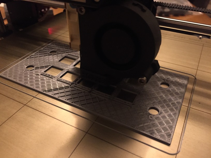
Here is a couple of camera phone shots of the printer working it’s magic on the front panel:

So, above I mentioned the profile piece I prototyped and printed. When I confirmed that it fit the desk as expected, I doubled them up in TinkerCad and added some ‘cross beams’ to put them the proper distance apart. I cut a piece out of each of the sloped beams, where the panel would, if I measured everything okay, slot in.

It was 2am when I finally made it home. I could not resist pulling all the switches from my earlier template and fitting them into the panel.

View from the front. The panel with the switches installed is the 3rd print. The second print is below it and the initial prototype is off to the right. The 2nd print had a curling problem on one corner, so we did a third after increasing the bed temperature and cutting the model up into more, thinner Z-slices.

If you look at the 2nd print (bottom) you will see little cut-outs above and below the switch positions. My thinking was to have a small, thin layer on the bottom (the front of the panel), with a void behind it with a series of LEDs inside the box. The thin layer of the print in those voids allows the light to shine through. After the printer is upgraded with the multi-filament I plan on replacing these voids with clear material and pushing them through to the surface. It might make a neat effect ![]()
Here is the switch panel sitting in the cutout section of the desk template. If fit exactly as I had hoped ![]()

I spent a couple of hours in TinkerCad today tuning up the switch panel and filling out most of the desk box as best I could. I have to put in some screw holes and something for the screws to screw into and decide on the final height of the box.

Next step is to pause the box design and wait until I have some idea if the electronics will fit or if I need to increase the height of the whole thing to accommodate.
I ended up getting a Teensy LC board instead of my planned Teensy 2 board (so I could make use of @Troll’s knowledge with his A DIY Radar Controller - #80 by Troll experience). But, goes to show, researching the Teensy first would have let me know that the boards are not pin-compatible. That’s okay for my next step, prototyping the electronics on a breadboard, but it means I am going to have more questions ![]()
I expect that the next phase is going to take some additional time to work through. Before I start, though, I have a couple of questions for people in the electronics know. I have a Saitek Throttle Quadrant that died on me a year and a half ago. It created problems whenever it was connected to the USB port on my PC. So, I pulled it apart ![]()
What I am wondering is: how hard would it be for me to hook up the axis devices, in their shell, to the Teensy and pass them on as axis inputs?

Basically, I am considering putting them back into their enclosure and running the wires into the Teensy controller and wiring them in as 3 axis analog inputs. Does this make sense? What are the wires above (Red = power, Black = ground, Yello = ?)?
In the next picture, what is the C23/C24 component on the board? Capacitors?
