Jesus… the quality of the print is phenomenal.
What’s the printer again?
1 Like
It’s a creality Ender 3v2 with some modifications. I think it’s replaced by the Neo, which has some of the mods I’ve added. Automatic bed leveling being one of the more important.
I also have a direct drive extruder and a better hot end.
That said, the printer worked great out of the box, although assembly was required.
But you know… Oh! Look…! A rabbit hooooooooooooleeeeee…. ![]()
4 Likes

OK NOW YOU CAN PRINT A 3D PRINTER!
1 Like
So…
I came across a smart fella on the VP force Discord server, who had a good idea.
Total redesign! Pictures coming soon.
The short version is that I will 3D print almost everything but the bearings.
And I don’t have to hang one of the FFB motors so it moves with the pitch axis.
This will decrease the mass and thus the rotational inertia considerably.
I have also received the Creality Sonic Pad and Installed it yesterday.
The Sonic Pad enables much better control of the 3D printer as it runs on the Klipper Firmware.
This is the first print for my FFB stick.
It’s the Roll axis link arm, printed in carbon fibre reinforced PETG, that is incredibly strong. I have added threaded inserts into the small holes.

3 Likes
Do you find the carbon-filled PETG to be worth the extra cost and wear on the printer?
As I understand the advantage lies in temperature resistance rather than mechanical properties per se, unless you have a continuous fiber system.

Hard to answer, really… I haven’t done any scientific studies. I’m using Add:North RigidX CF infused PETG. It prints really well, but at slightly lower speeds. In this particular case I’m dealing with long parts that will be put under some bending strain, so I want the parts as rigid as possible. I like the way the RigidX looks and it’s hard as a brick. I could change the design slightly and use a softer material, but I went with the toughest material I know of. There’s no such thing as overkill… ![]()
For one off projects like this, the material cost isn’t really an issue. If I were to make longer production runs I’d probably consider Nylon or regular PETG. As long as you have hardened nozzles, the wear is manageable. But again, for longer runs, maybe not.
1 Like
Pics of the new design.


The timing belts aren’t shown, nor is the framework for attaching the motors. The covers for the base framework is also missing in the pictures.
This design has the advantage of keeping the motors stationary and transfers the roll movements via a push/pull rod, to the pulley. I use a larger pulley for pitch, as the moment arm is longer in pitch than in roll, for this design.
1 Like
Been printing away lately.
The Carbon Fibre PETG gave me some issues.
The hotend of the printer suffered from large temperature fluctuations. I set it to print at 260°C but temps could vary between 240 and 270. I think this also caused some layer shifting in the prints. After some googling I managed to tune the thermistor of the hotend, so it became more stabile. There were also an issue with the extruder motor. It extruded about 70% of the required amount. Once I tuned that in, the printer started to behave…
But several misprints come at a cost. When I was going to print the upper part of the stick, I switched to regular (cheaper) PETG plastic. I will re-print it in the green CF PETG.
I have divided the parts up to make printing a bit easier and to avoid having to use too much support structures. 3D printers struggle with printing in thin air, so you need a support structure for overhangs and I try to avoid this with Carbon Fibre prints.

3 Likes
All the parts printed in Carbon Fibre infused PETG plastic and joined by superglue and a large wooden screw, for added strength…
I provided a hole through the parts, for this purpose.
I sanded the parts and actually used superglue and accelerator, to fill gaps and visible layer steps.
This is a technique I learned building plastic scale models, but as superglue used to be rather expensive, I have used the method sparingly. These days you can buy large 2oz bottles, with accelerator, dirt cheap. So, I just apply glue and distribute it with an old credit card, or similar. When satisfied I apply the accelerator and then wetsand any excess glue. Works great! But do be careful with the fumes though! CA glue is powerful stuff…

4 Likes
Here’s the same part with a couple of layer of matte clear laquer.
The laquer gives the surface a more uniform sheen and depth of color.

4 Likes
good work. keep em comin. at least I can watch while I dont have time to DIM ![]()
1 Like
A couple of 3D printed HTD-5 15mm pulleys.
I printed each pulley as two halves to be able to build in two M6 nuts in the pulley. These nuts will hold screws that attach the timing belt to the pulley. Huh? Yeah, the pulley will only turn +/-20° so the belt doesn’t have to rotate several revolutions around the pulleys. This simplifies timing belt selection and tensioning, as I can just cut the belt at the closest “cog”, punch a hole in it and screw the end down.
You may wonder why I chose to print one half in black and the other white. The best explanation I can come up with is; Why not? Or perhaps that it seemed like a good idea at the time and I was left unsupervised…

2 Likes
I was going to use a carbon fibre print as a link for the stick and roll coupling, but space is limited and if I use two alu plates, I can save some…
And it will be more wear resistant. ![]()

5 Likes
It’s starting to come together…

It’s cramped in there. There will be covers closing this unsightly hole.

Naturally, the flange bearing must be covered by acceptable means as well…

7 Likes

ConTrollR is coming along nicely, you have a seriously cute pooch, but I’m loving the grain and colour of your floor and would like to know what wood that is please?
1 Like
Unfortunately it’s a completely fake laminate floor that’s about to be substituted for something new and better. We moved in here a year + ago and the floor has been here since they built the house in 2002. The laminate is probably a metal click type as I suspect the metal attachments underneath has come loose in places.
2 Likes
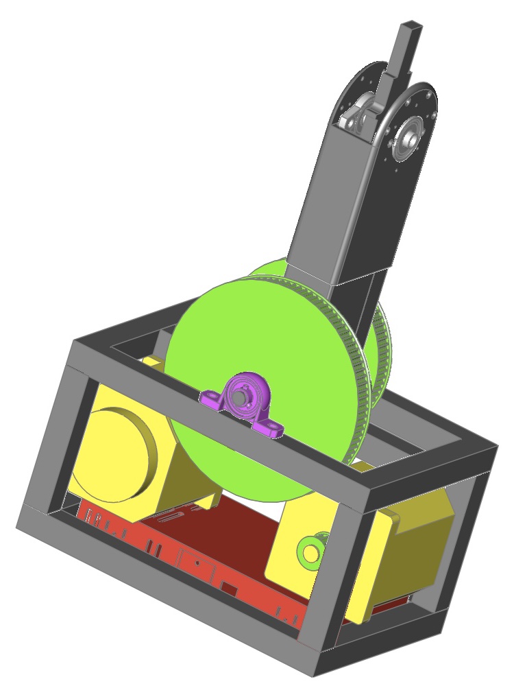
Mounted the pulleys.
The left pulley is the pitch pulley that is secured to the stick. The assembly is held in place with black electricians tape to keep the stick from falling over.
The pulley to the right is the roll pulley. It will be connected to a pushrod, going up to the roll handle.

3 Likes
What a nice clean design! As always, a joy to watch your work. Thanks for the opportunity. ![]()
1 Like
Testing out the length and throw of the stick.


I will shorten the stick about 3cm and maybe move it a couple of cm forwards…
9 Likes