A new build document to reflect the changes is required
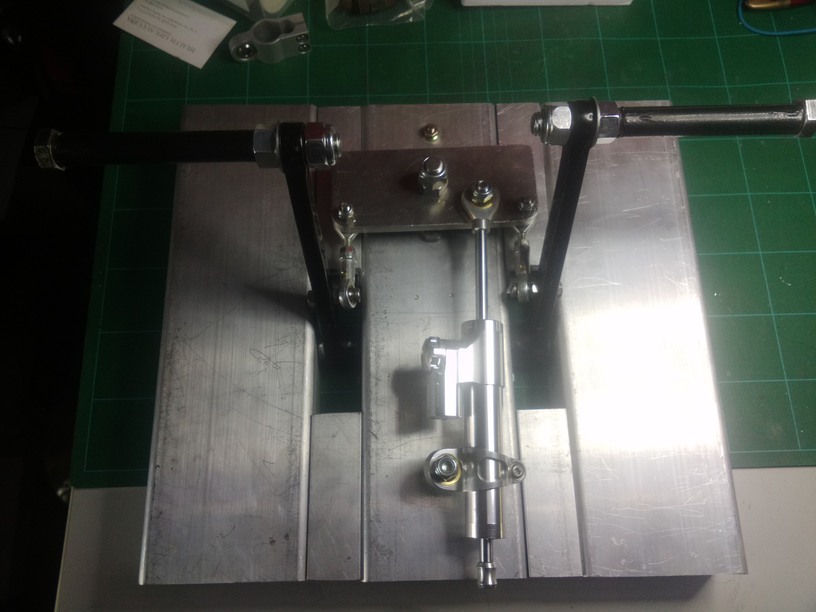
but basically I’ve taken out the legs and made the entire base from the centre beam structural C channel
overkill - yes
indesctructible - yes
heavier - yes
depending on your floor though will still need to be secured in place.
this has made the pedals maintain an axis regardless of the self aligning bearings…which were allowing them to sag outwards…awful
i repurposed some of the legs from the former set to act as spacers, Ive aligned these to the top, but you can get rectangular box section the same height as the C channel which will be far better suited
so it will be flush top and bottom
Im still working on a bettter solution for the pivot plate/bolt arrangement… having all sorts of issues with the TLE5010 sensor…its driving me friggin crazy and im grounded until its sorted - so doubly pissed.
Hey Troll
Ive been trying to beef up the design around the pivoting bolt and plate to reduce any backlash/slop, but I am unable to obtain the level of output results from the TLE5010 as I got when i had the less rigid assembly i started out with…
Its got me wondering if I havent done something wrong with the config…
I put in continuous left and continuous right inputs repeatedly but from the graph attached its is clear that there is some major spiking/jitter occuring… and I cannot eliminate it. (not overly competent in what I’m doing either.)
I originally had it set to auto with centre in the auto-calibration field
i have since tried auto w/o centre, saved with centre as well, no discernable variation
i was originally set to 8bit precision, but a colleague helping me out upped it to 10 and added the x2 filter to get the better output which we were able to capture the graphed output from
he is very good with electronics, but had to admit he was operating at the limits of his knowledge/experience in regards to the TLE5010, so I am bowing to the experts for ANY help that might come my way
thanking you in advance
cheers
First, try changing your PID (3333) to something else, and resave to the device.
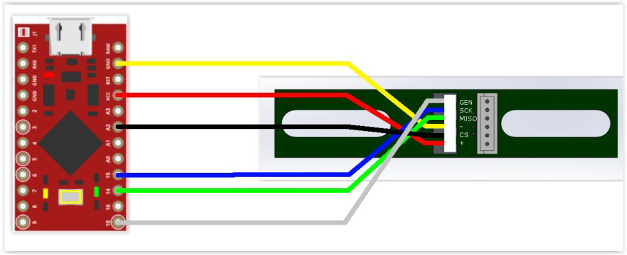
I have seen TLE sensors behaving badly when I have used several of them. The solution was to remove a resistor on the TLE PCB, and put a resistor between VCC and MISO, on the Teensy/Arduino controller.
Try the PID first, and I’ll dig up the details for the resistor.
Also, you are using an old MMJoy2 version. Might be a good idea to download the latest version, and update the firmware.
Edit:
This may be the magnet is offset. There is a setting for that, or you could try turning the magnet approx. 90°.
as I think I’ve said before, the mechanical stuff I can nut out, but the electronics are all a bit beyond me, but I’m slowly grasping some basics, and I have to keep leaning on friends with more knowledge horsepower than me…
Yep, I put my money on a floating voltage existing in the data lines causing garbage to be interperted as a signal. Put 10k resistors between the data lines to ground if they are normally low and any line that is normally high put a 10k resistor between that and VCC.
What happens when you close a line between the micro controller and the sensor, is that a transistor stops sourcing or sinking it, but this leaves a residual voltage in the line that can float between ground and VCC causing ghost signals to be read.
edit, just realized that Troll and I are saying the same thing!
TAS, we had an oscilloscope and high end multimeter running off them and results on the scope were pretty clean
The results in the graph were fairly consistent too, perhaps too consistent to be attributed to any stray voltage, which would be more sporadic wouldnt it?.
*** Really appreciate all feedback - I apologise in advance
for stupid questions ***
Have been working with gadget on this.
The scope trace was pretty clean, didn’t analyse it deeply, just had a visual on the waveform with a DS1104Z
My money is on calibration or magnet position, agree that updating MMJoy FW would be wise.
apols
graph is full left and full right inputs of pedals
slight variation in width is speed of input ( I was using my hands)
but the spikes/jitters seemed to be occuring at same intervals in travel
out towards the end of the travel/stroke length
an additional note; I have 2 x TLE5010 sensors, and I replaced the original with the spare today, to eliminate that from the source of the problem.
Alright, so we can eliminate noise if the scope trace is clear. That leaves us with either a bug in the software which I can’t really envision, some sort of configuration error as Troll described, or the magnetic field not being strong enough. Have you looked at how much the magnet moves compared to the sensor, and does the field perhaps becoming too weak to get an accurate reading at the sensor itself?
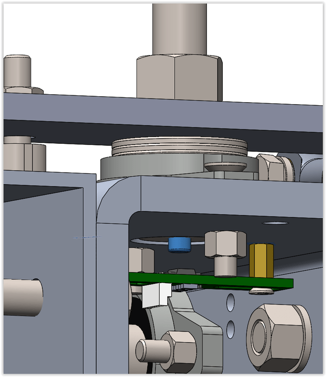
magnet (blue) is mounted in small recess turned into the head of the bolt
TLE5010 is mounted on hex spacer nuts seated in drilled & tapped holes
pivoting bolt is sitting in a ‘collared’ self aligning bearing
I have packed the shaft of the bearing with stainless steel washers up to the pivot plate, to prevent it from allowing any teetering between the bearing and the pivot plate, its enough to stop any slack but not enough to seize the bearings ability to swivel at all.
As a safeguard I have also placed a piece of plywood behind the pivot plate to prevent any teetering, Im sourcing a piece of pactene sheet to shape a more suitable solution
original plate was a 12mm hole and bolt simply passed through and nuts secured it in place, I replaced this pivot plate with another identical except that I tapped the pivot hole to 12mm and the bolt now tightens down the plate and a second nut locks it in place.