G’day @marvin
things have slowed considerably with lock down here.
we are currently not able to collaborate on any testing work to prove the design
however in the mean time we have built another small test board to send off
this will help us confirm our BoM list and the necessary pick & place file for production
better we learn any potential caveats on a cheap demo board, (that will also have a function/purpose that can be tested to confirm it works) than attempt to do the MMjoy board off the bat. There was several faux pas on our last demo board that we didn’t realise would be an issue, so its all a learning curve.
Regarding flashing the unit it should be very easy, (no more difficult than flashing a normal promicro board with an ATMega32u4 chip. It will probably run with an arduino boot without issue. We’ve designed this to assist the less technically skilled, whether physical/soldering or logical/programming (mmjoy takes away a lot of the headache).
We are pretty keen to get it done & dusted, but covid is interfering with our normal capacity to operate. We are both retirees with not a lot of cash to throw around at it, so we are just doing what we can, when we can, which at the moment is the issue…when, as we sit through a second wave of pandemic here in Victoria.
Apologies to everyone interested in the card. We still intend to produce it.
but as stated early on, its nothing that isn’t already available with existing hardware;
*arduino clone, Pro Micro ATmega32U4
*& Shift register dev board
we are just aiming to simplify it for the flight sim hobbyists.
@gadget I fully understand and being in Europe it might have been better to work from your prints and get a couple shipped from a manufacturer directly to me.
Having the JST connectors on the board would have been easier, both with logical grouping and ease to connect without needing to solder onto the board.
wrt the 2 links you posted, my understanding is that the shift register dev board is just an easy way to plug in (and extend) your buttons that’s configured as a shift register (6 sets with 4 buttons if I look at it correctly) and can just be daisy chained as you need.
On the first link I can’t quite figure out how the series of pins that’s included should be soldered (some photos it looks like there’s already solder in them and some don’t). If they are without solder it’s just clamp the things in place and gently solder 1 pin at a time from different areas on the board and giving breaks for the board to cool down.
Which brings me to the another, if I take 3/4 HAL sensors on a board, how much ‘button space’ will there be remaining. I’d likely end up with 2 ‘heavier’ setups for them. The first having 2 axis and 1/2 thumb ‘stick’ style controls + buttons and another that will have 3/4 axis, buttons and potentially a thumb ‘stick’ (before my PC hardware interrupted me I was trying to determine HAL sensors and their needed inputs)
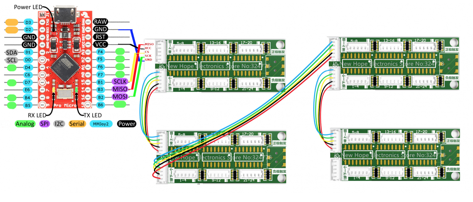
if your using the shift register dev board, it will only require 5 wires back to the pro micro
whether your using 2 buttons or 20 (24 per dev board)
Personally I have connected up to 4 dev boards off the one pro-micro for a single switch panel, but tend to now keep it down to 2 dev boards per pro micro (48 swtiches)
This all still only requires 5 wires coming back to the pro micro (none of which are really data input pins - GND, VCC, CS, SCK & MISO)
which leaves plenty of room for connecting analogue axis inputs to the pro micro.
On our gucci little MMjoy board this is achieved by 5 tracks running between the ATmega32u4 chip & the shift registers chips, saving you the headache of soldering them on & then having to fault find any connectivity issues (make sure you have a multimeter on hand)
Note: on the original dev boards we got, the pin labels were incorrect & after much trouble shooting we discovered that on the connector back to the pro micro board, we had to pull the plastic connector recess off, turn it 180 degrees, then replace it, all without damaging the pins. Apparently this has now been rectified - but having a multimeter on hand and knowing the pin assignments of the 74HC165 chip will allow you to correctly identify any issues.
@marvin, if I may be so bold to intrude on @gadgets thread here, I have some teensys with shift regs, if you don’t want to wait. Not as polished as the one Gadget et. al. will make, but they work.
Oh hell yeah
completely forgot, @Troll has his own boards he created ages back
(mine isn’t an overly new / original idea)
he’s the man.
there are several features about his boards that I really like
& incorporate things that I actually tend to try to get new guys to take on as a kind of ‘best practise’ when starting out
#1 female pin header mount for the teensy, if you have a (cheap) modular board that will fit onto your project board, then provide a means of removing it in case it fails, it will make for a very simplified/easy swap & go process in the case of a component failure.
#2 pin headers for connecting multiple lines in to the same input, sometimes you will need to connect multiple items to the same pin on the chip, but you often only have the one pad to solder to, @Trolls project board as a line of pin headers, each attrributed to the same input pin that you can solder to as required. Also pin headers are excellent mount points for the smaller gauge wires that often come with the shift register boards, which makes for difficult soldering and easy breaking when the wires are continuously flexed back & forth.
The pin headers allow for heat shrink to be applied to the wire/solder/pin header in a manner that will provide some physical rigidity and protection to the solder point (as well as being able to use breadboard leads to connect temporarily when testing).
#3 screw mount holes on the project board, often overlooked, but small component boards like the teensy, pro micro & even the dev shift register boards either dont have any means of mounting the board or screw holes that are too small and too close to the edge of the board to provide any sort of solid mounting option. A project board that includes a mounting options is often a well considered feature.
This is truly wonderful example of a simple elegant & utilitarian design.
I’ll take function over fashion any day.
Simplicity is the ultimate sophistication. Leonardo da Vinci
I’ll take this further in troll’s DIY controller thread, I’ve anyway been meaning to post some of what came up here there and a few other things (though not gonna be able to today)
I don’t mean to hijack the thread. Just curious if there was a central repository of PCB designs on this forum. I have a knack of finding the PCB’s after I needed them!
BTW, The work that you all have done is absolutely fabulous and inspiring!
Greeting Gentlemen
whilst everythings been locked down here, I’ve been busy
I would first like to say that development hasn’t stopped , but we have taken a slightly different direction.
We had begun tinkering with some A-10C panels and got into it pretty deep when I stumbled upon an idea and we are working on bringing that to the community.
However as part of that products development, we still intend to produce a board similiar to the one I have been working on here with a few major differences:
The MCU will now be an STM32 chip which introduces much better capabilities & strengths as well as being much better value for money.
The STM32 is considerably more populated than an ATMega32U4 so we are working through coming up with a minimal hardware requirement configuration that we can apply to the PCB design and then proceed with further project development.
This board has kind of taken a back seat at the moment, but it will still be developed as part of the development of our new main project & by nature of that pipeline it will be finished prior to the main projects completion.
We still see it as the primary reason we started down this rabbit-hole and full intend to see it through.
In fact it will be actually be a prototype test board as we proceed with the larger project R&D.
I will provide updates as we pass any major milestones worth mentioning.
please keep in mind this is all a hobby to each of us involved and we are running it concurrently as time permits along with everything else we are doing in life.
In the meantime if anyone wants to make a switch box I am more than happy to share how i did it using available ATMega32u4’s and the shift register dev boards mentioned above.
Great news, @gadget!
However, you are beginning to venture outside my comfortzone by changing soft and hardware… But that’s ok! I’ll just buy your boards from now on…
So, get back to work!
I have a question, please. First of all, let me admit I am no Arduino coder nor electrically savvy. I just want to build my own button box for the flight simulator without any intention of playing further with Arduino once done. I was close to start working on the DIY 32 button box, which was well documented on many channels and I felt confident enough to make it work although I was not happy with the limits of 32 buttons/board. But when doing some more research, I saw your comment on the xsimulator.net forum regarding the shift register and it made me reconsider my intention. I like your suggestion more, but I am wondering:
A known issue with the 32 button box is the key conflict. I am assuming this is not the case using the shift register as all button has their own pins, correct?
Does the shift register board support the rotary encoders? If so, how do you wire them?
hi @pav3lm
i apologise for the long hiatus, but i ahve been busy doing lots of other things
to answer your questions:
the shift registers combined with resnets allow for each pin to individually work, beyond 32 buttons i believe, i have only ventured to 2 of the dev boards pictured, which equals 48 buttons total
yes the shift register accepts rotary encoders, but (obviously not potentiometers)
each pin is wired to its own data pin & to the associated (shared) ground for those pins
you could either have the entire encoder on the same shift register & shared ground
increase,decrease, push & the 2 gnds (shared) or across 2 seperate wiring looms
increase,decrease, gnds (same shared) + push & the other ground pin to the ground shared with this data pin
MMjoy takes care of all the difficulty for you, all you need to do is tell it which type of shift register chip you are using, when mapping the buttons, you can indicate the increase/decrease as being an encoder, rather than a button.
again apologies for the delay, but im now back
hello everyone, @here
my apologies for my lack of presence recently, RL getting in the way unfortunately, but now i am back again.
I am still working on this functioning board, but we have moved our focus slightly
we are now looking at the STM32 chipped bluepill as the base board instead of the promicro ATMEL32u4 chip
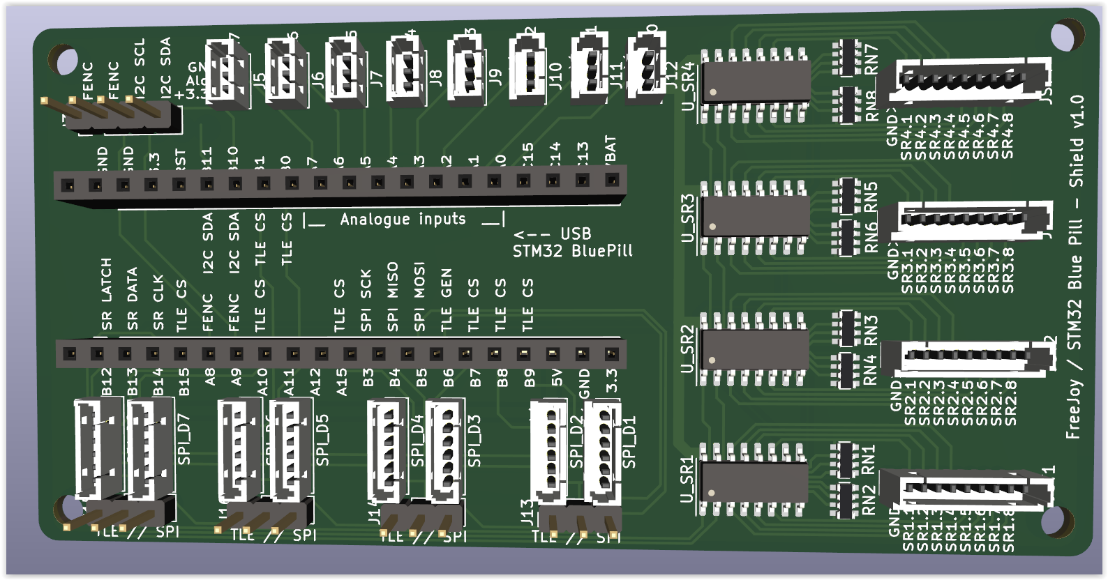
& because of this have moved from MMJoy which we received permission to utilise for non-commercial use, to Free-Joy which supports the STM32, which is a more capable chip
higher resolution axis etc.so the delay has essentially been a win-win
we are also working on a few other custom PCBs to help me put together my apache simpit. which will allow me to daisy chain I/O cards for DCS-BIOS connectivity & function
so in short, its still coming, its being worked on & most importantly focus has returned to it once again
touch wood we should have a working solution in a few months at worst.
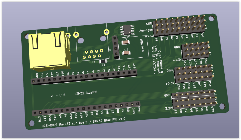
PS: also rather than building a custom board & reinventing the bluepill board we are quite likely just going to make it a daughter board … its actually cheaper to buy a bluepill board than to source the STM32 chips… crazy how the world works sometimes.
so hopefully we can provide this through a dedicated config file or simple how-to documentation.
a little bit more testing to be performed, but it is very close to getting finalised & submitted for production
this board will eliminate having to solder anything directly to the I/O board or shift registers
& only require you to solder the ends of the leads (or wire extensions) to the button/switch of your choice. Hopefully simplifying the headache of creating a switch/button box or joystick from scratch
easily applied to flight sims, car sims, space sims… whatever. anything where you would benefit from craeting your own custom button box/input controls.
update!
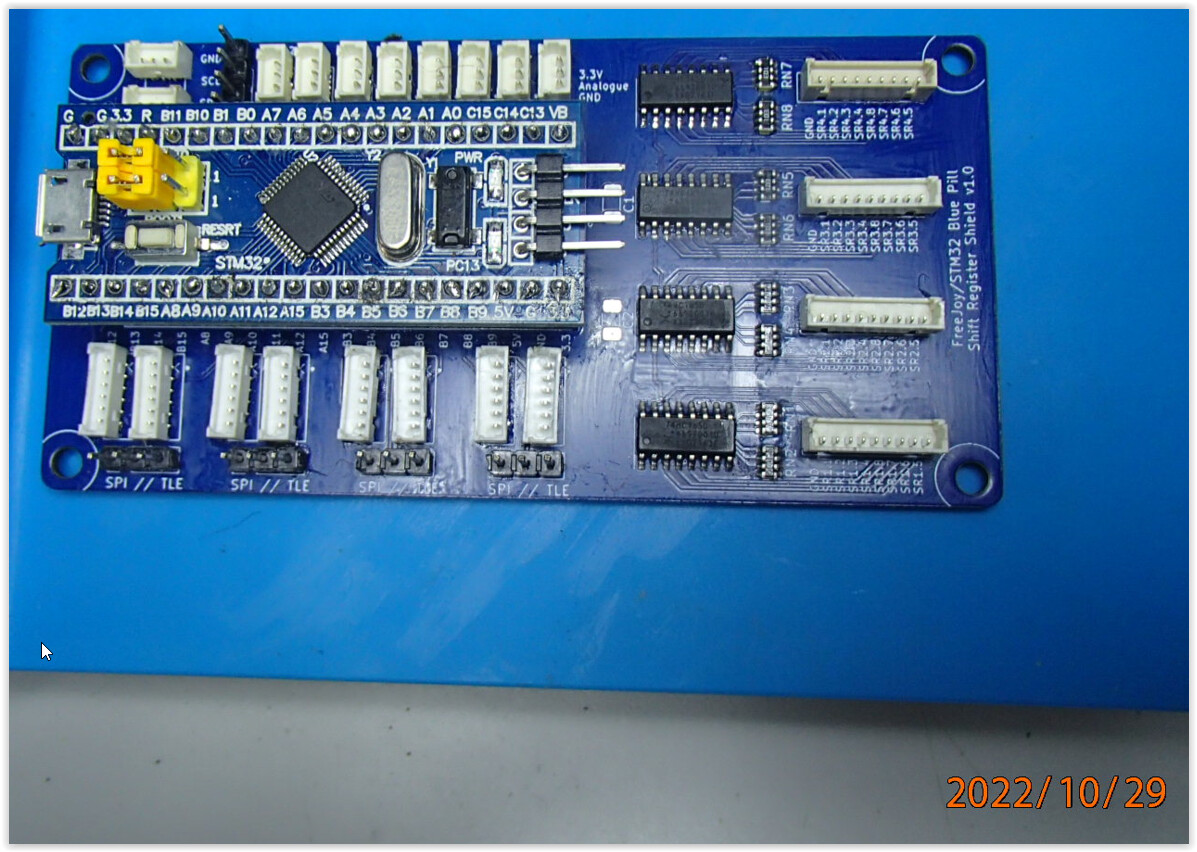
protoypes have arrived, now just need to solder them up & test up all the various connection types.
we have already made a few considerations for redesigning to allow for easier production as well as improved features.
OK, so some progress has been made, finally received most of the components & had a crack at soldering the tiny SMD resnets… yes they are a complete ■■■■■■■ to hand solder.
But in the end, got used to the technique & had some decent results, all come down to the preparation, the adequate tools & the right solder paste, stuff i tried to use initially was just shite…
any-hooo…
excuse the photos, I haven’t had a chance to clean the board up properly yet, ultrasonic bath yet to occur.
the eagle eyed amongst you may have noticed the 2 missing components, these are for capacitors, waiting for some from one of my partners (in depravity & PCB design ) to ‘lend’ me a couple…
Note: given the frequency & regularity in which some of our associates have bricked their bluepills, we have decided NOT to proceed with these shield boards above for other consumers, & we will just leave these as a prototype for testing.
We will however be producing a dedicated board, that looks pretty darn close to the one you see here (exact physical footprint), except that there will be no sockets in the middle to mount a bluepill, instead we will be integrating all the STM32 bluepill board components onto the Freejoy boards, with a few upgrades of our own thrown in for good measure (to reduce likelihood of similar bricking of the standard bluepills).
Once we have tested this set & proven the basic board, we will then get a prototype/test batch of the dedicated board produced to test. If successful that will be the production board!
So looking forward to seeing that come to fruition.